DESCRIPTION OF FEATURES
|
|
|
|
|
|
|
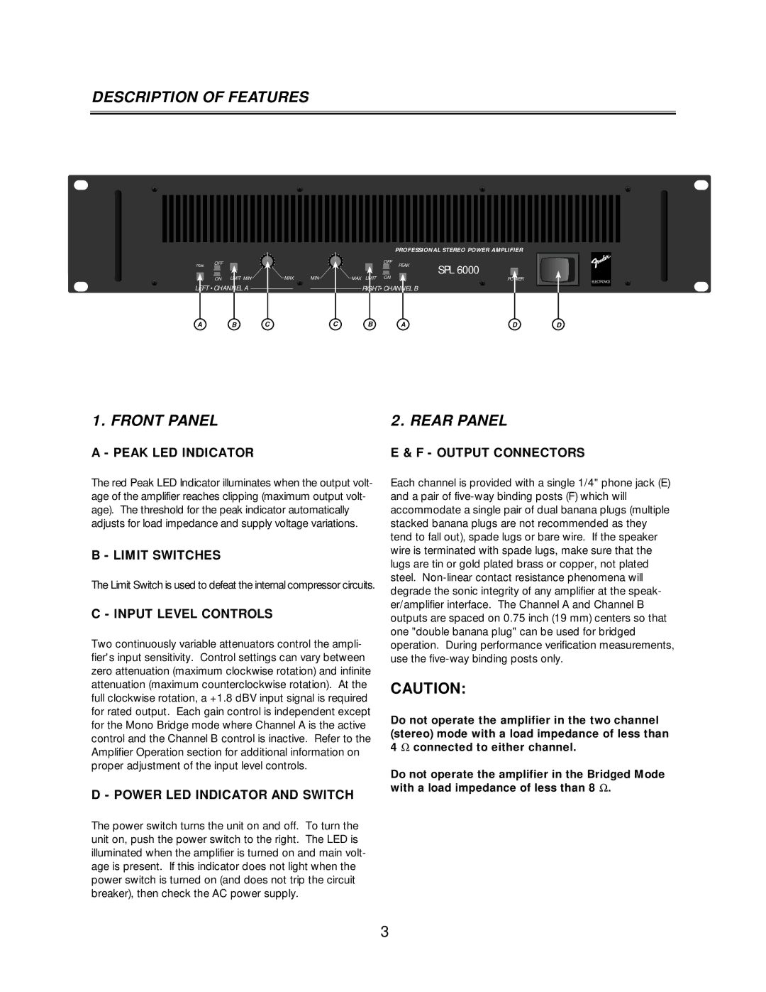
| PROFESSIONAL STEREO POWER AMPLIFIER | |
PEAK | OFF |
|
|
|
|
| OFF | PEAK | SPL 6000 |
|
|
|
|
|
|
|
| ||
| ON | LIMIT MIN | MAX | MIN | MAX | LIMIT | ON |
| POWER |
LEFT •CHANNEL A |
|
| RIGHT•CHANNEL B |
| ||
A | B | C | C | B | A | D |
ELECTRONICS
D
1. FRONT PANEL | 2. REAR PANEL |
A - PEAK LED INDICATOR | E & F - OUTPUT CONNECTORS |
The red Peak LED Indicator illuminates when the output volt- age of the amplifier reaches clipping (maximum output volt- age). The threshold for the peak indicator automatically adjusts for load impedance and supply voltage variations.
B - LIMIT SWITCHES
The Limit Switch is used to defeat the internal compressor circuits.
C - INPUT LEVEL CONTROLS
Two continuously variable attenuators control the ampli- fier's input sensitivity. Control settings can vary between zero attenuation (maximum clockwise rotation) and infinite attenuation (maximum counterclockwise rotation). At the full clockwise rotation, a +1.8 dBV input signal is required for rated output. Each gain control is independent except for the Mono Bridge mode where Channel A is the active control and the Channel B control is inactive. Refer to the Amplifier Operation section for additional information on proper adjustment of the input level controls.
D - POWER LED INDICATOR AND SWITCH
The power switch turns the unit on and off. To turn the unit on, push the power switch to the right. The LED is illuminated when the amplifier is turned on and main volt- age is present. If this indicator does not light when the power switch is turned on (and does not trip the circuit breaker), then check the AC power supply.
Each channel is provided with a single 1/4" phone jack (E) and a pair of
CAUTION:
Do not operate the amplifier in the two channel (stereo) mode with a load impedance of less than 4 Ω connected to either channel.
Do not operate the amplifier in the Bridged Mode with a load impedance of less than 8 Ω .
3