- 2.2 |
| 2.1 | ||
2.3 |
|
| 0 | .8 |
|
| 0. |
| |
| 0. | 6 | ||
| 0. | 4 |
| |
+ | 2 |
|
| |
|
|
|
| |
temperature monitoring device is fitted to provide protection against overheating (burn-
Do not work with the planer if the electronic control is defective, since this may lead to ex- cessive speeds. A defect in the electronic con- trol is indicated by the absence of a smooth
Machine settings
![]() Always disconnect the plug from the power supply before making any adjust- ments to the machine or installing or remov- ing any accessory!
Always disconnect the plug from the power supply before making any adjust- ments to the machine or installing or remov- ing any accessory!
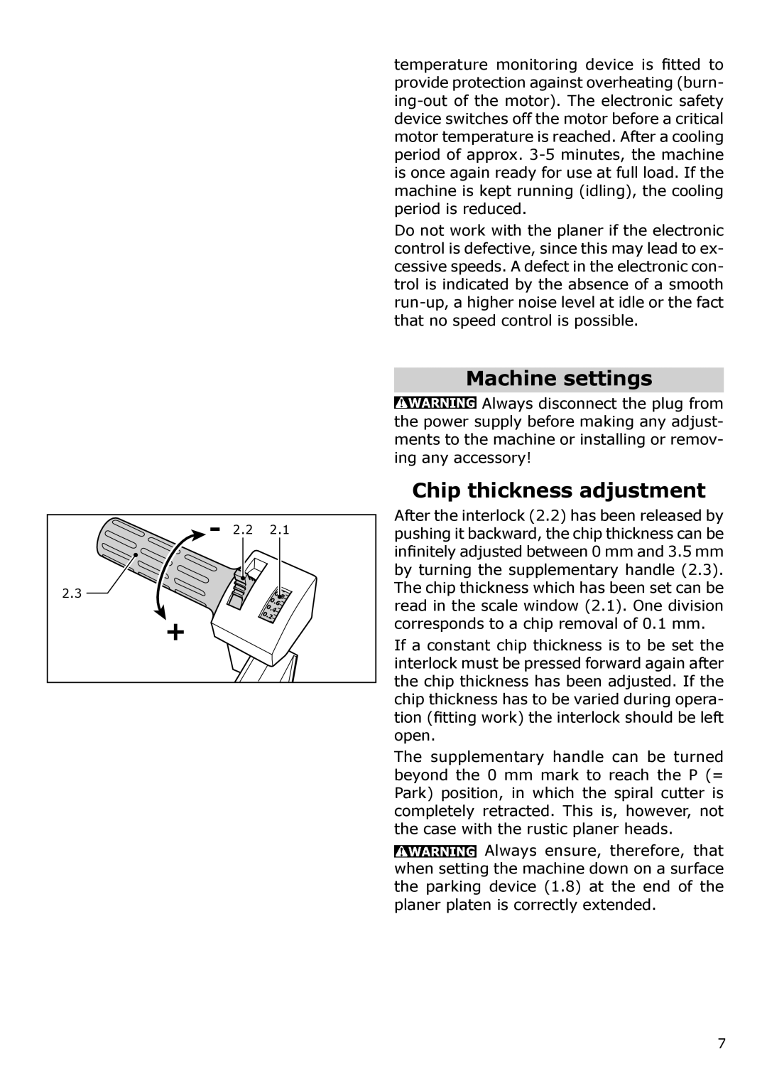
Chip thickness adjustment
After the interlock (2.2) has been released by pushing it backward, the chip thickness can be infinitely adjusted between 0 mm and 3.5 mm by turning the supplementary handle (2.3). The chip thickness which has been set can be read in the scale window (2.1). One division corresponds to a chip removal of 0.1 mm.
If a constant chip thickness is to be set the interlock must be pressed forward again after the chip thickness has been adjusted. If the chip thickness has to be varied during opera- tion (fitting work) the interlock should be left open.
The supplementary handle can be turned beyond the 0 mm mark to reach the P (= Park) position, in which the spiral cutter is completely retracted. This is, however, not the case with the rustic planer heads.
![]() Always ensure, therefore, that when setting the machine down on a surface the parking device (1.8) at the end of the planer platen is correctly extended.
Always ensure, therefore, that when setting the machine down on a surface the parking device (1.8) at the end of the planer platen is correctly extended.
7