-Pull the unlocking ring (2.3) forwards, press the chuck onto the drill spindle up to the stop and release the unlocking ring.
Removal:
-Pull the unlocking ring forwards and remove the chuck.
Changing tools:
-Turn the clamping sleeve (2.2)
(Note: the spindle is automatically locked when the machine is switched off).
-Insert the tool into the chuck.
-Clamp the tool by turning the clamping sleeve clockwise. Always make sure that the tool is clamped centrally in the chuck.
Angle attachment DD-AS
The angle attachment permits work (drilling, screwing) vertical to the machine’s longitudinal axis.
Fitting:
-Place the angle attachment on the drill spindle and turn until it catches in the desired position (Note: The angle attachment can be fitted in 16 different angle settings).
-Lock the angle attachment by turning the fastening ring (2.7) tightly clockwise.
Removal:
-Turn the fastening ring
Fitting / removal of chuck on angle attachment:
The chuck is fitted on the shaft (2.6) of the ang- le attachment in the same way as on the drill spindle of the machine.
Eccentric attachment DD-ES
The eccentric attachment is used to hold bits. It allows screwing close to edges.
Fitting / removing the eccentric attachment:
The eccentric attachment is fitted / removed in the same was as the angle attachment (see DD- AS).
Changing tools:
Pull the unlocking ring (2.8) back and remove the tool and/or insert the new tool.
CENTROTEC WH-CE toolholder
The CENTROTEC toolholder enables rapid changes of tools with CENTROTEC shafts.
Danger of injury! When changing tools, handle the tool and its sharp cutters with special care and wear protective gloves, if necessary.
Do not fit CENTROTEC tools at the round shaft section in a conventional chuck to prevent damage to the shaft.
Fitting
-Pull the release ring (2.11) forwards, place the toolholder as far as it will go on the drill spindle (2.5) and let go of the release ring.
Removal
-Pull the release ring forwards and take off the toolholder.
Changing tools
-To insert or remove a tool with CENTROTEC shaft, pull the green release ring (2.10) back. On inserting the tool, turn it until its hex shank arbour (2.9) locks in place in the hexagonal shank of the drill spindle, and push the tool into the toolholder as far as it will go.
Tool holding fixture in the drill
spindle
Bits can be fitted directly in the hexagon socket holder of the drill spindle (2.5) to make the machine lighter and shorter.
Charge battery pack
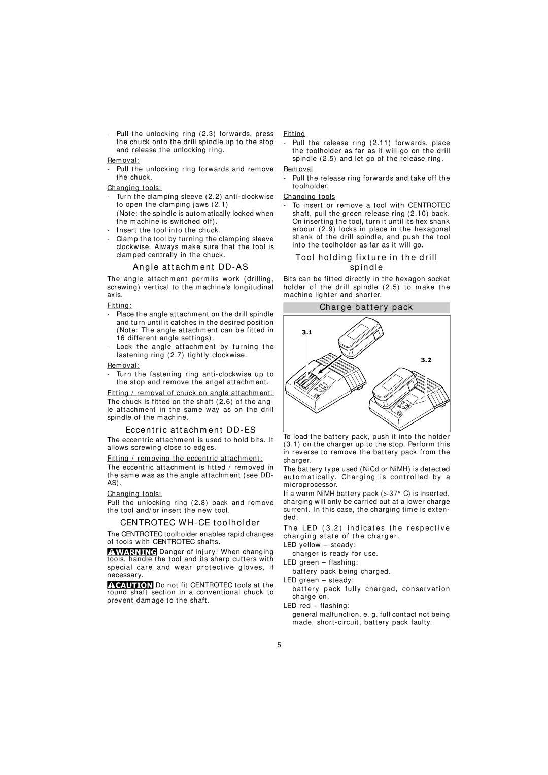
To load the battery pack, push it into the holder (3.1) on the charger up to the stop. Perform this in reverse to remove the battery pack from the charger.
The battery type used (NiCd or NiMH) is detected automatically. Charging is controlled by a microprocessor.
If a warm NiMH battery pack (>37° C) is inserted, charging will only be carried out at a lower charge current. In this case, the charging time is exten- ded.
The LED (3.2) indicates the respective charging state of the charger.
LED yellow – steady: charger is ready for use.
LED green – flashing: battery pack being charged.
LED green – steady:
battery pack fully charged, conservation charge on.
LED red – flashing:
general malfunction, e. g. full contact not being made,
5
