PV SERIES POWER VENTER: VERTICAL VENTING OPTION
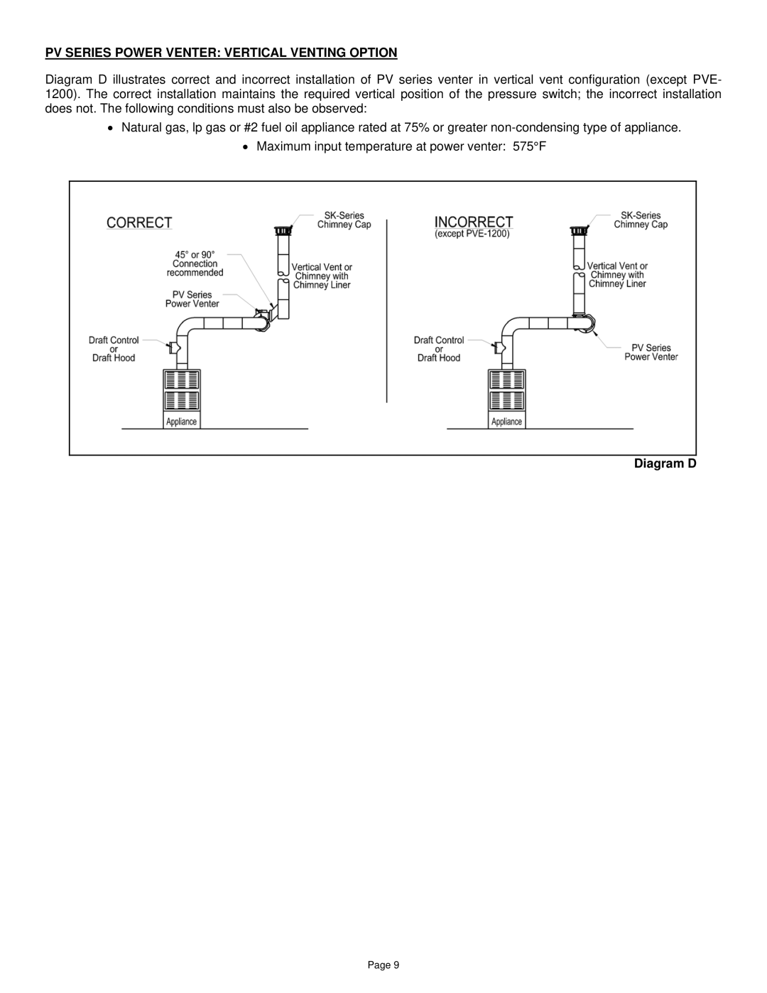
Diagram D illustrates correct and incorrect installation of PV series venter in vertical vent configuration (except PVE- 1200). The correct installation maintains the required vertical position of the pressure switch; the incorrect installation does not. The following conditions must also be observed:
•Natural gas, lp gas or #2 fuel oil appliance rated at 75% or greater
•Maximum input temperature at power venter: 575°F
Diagram D
Page 9