MULTIPLE APPLIANCE SYSTEMS
When using one PVO power venter to common vent more than one appliance, a Control Kit is required for each additional appliance.
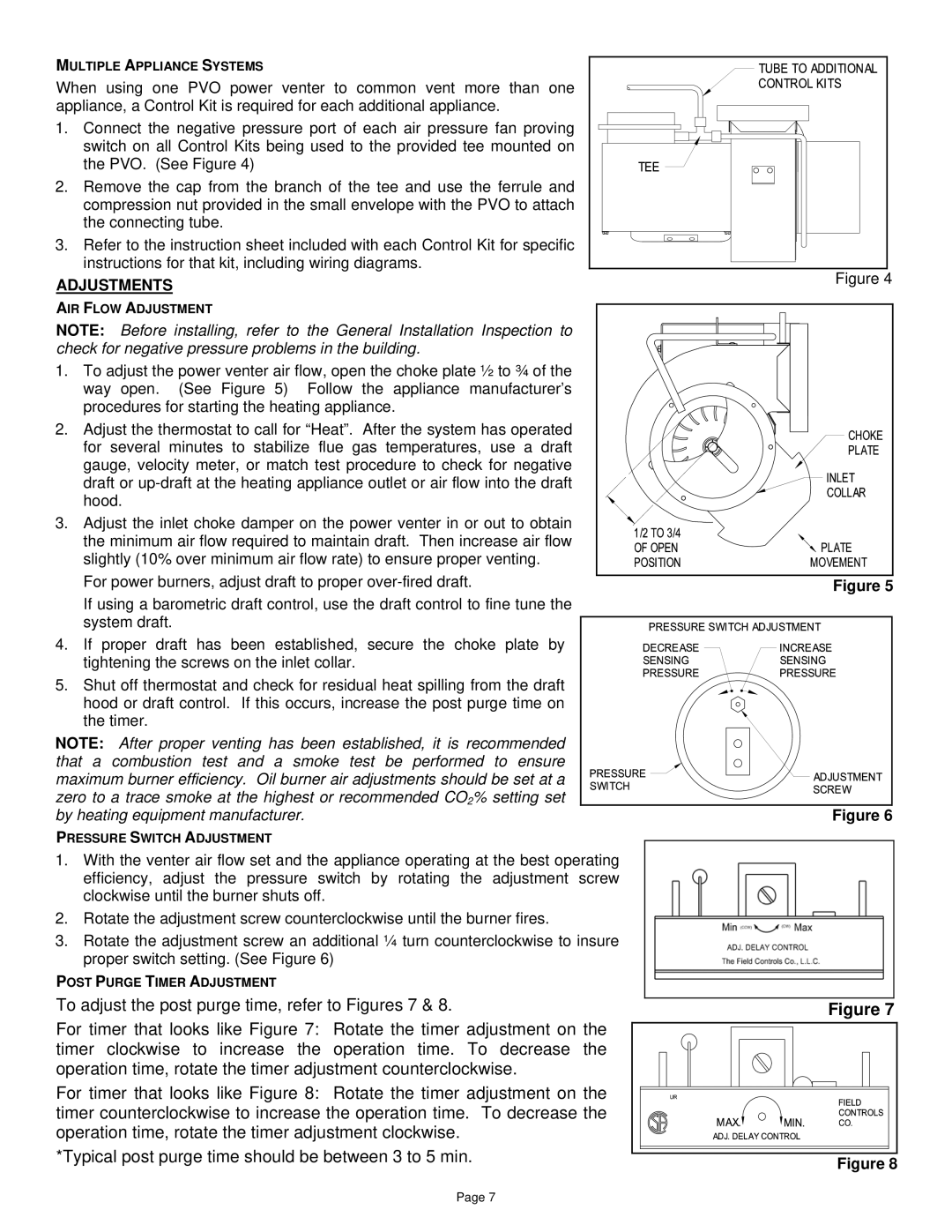
1. Connect the negative pressure port of each air pressure fan proving switch on all Control Kits being used to the provided tee mounted on the PVO. (See Figure 4)
2.Remove the cap from the branch of the tee and use the ferrule and compression nut provided in the small envelope with the PVO to attach the connecting tube.
3. Refer to the instruction sheet included with each Control Kit for specific instructions for that kit, including wiring diagrams.
ADJUSTMENTS
AIR FLOW ADJUSTMENT
NOTE: Before installing, refer to the General Installation Inspection to check for negative pressure problems in the building.
1.To adjust the power venter air flow, open the choke plate ½ to ¾ of the way open. (See Figure 5) Follow the appliance manufacturer’s procedures for starting the heating appliance.
2.Adjust the thermostat to call for “Heat”. After the system has operated for several minutes to stabilize flue gas temperatures, use a draft
gauge, velocity meter, or match test procedure to check for negative draft or
3. Adjust the inlet choke damper on the power venter in or out to obtain the minimum air flow required to maintain draft. Then increase air flow slightly (10% over minimum air flow rate) to ensure proper venting.
For power burners, adjust draft to proper
If using a barometric draft control, use the draft control to fine tune the system draft.
4. If proper draft has been established, secure the choke plate by tightening the screws on the inlet collar.
5. Shut off thermostat and check for residual heat spilling from the draft hood or draft control. If this occurs, increase the post purge time on the timer.
NOTE: After proper venting has been established, it is recommended that a combustion test and a smoke test be performed to ensure maximum burner efficiency. Oil burner air adjustments should be set at a zero to a trace smoke at the highest or recommended CO2% setting set by heating equipment manufacturer.
PRESSURE SWITCH ADJUSTMENT
1.With the venter air flow set and the appliance operating at the best operating efficiency, adjust the pressure switch by rotating the adjustment screw clockwise until the burner shuts off.
2.Rotate the adjustment screw counterclockwise until the burner fires.
3.Rotate the adjustment screw an additional ¼ turn counterclockwise to insure proper switch setting. (See Figure 6)
POST PURGE TIMER ADJUSTMENT
To adjust the post purge time, refer to Figures 7 & 8.
For timer that looks like Figure 7: Rotate the timer adjustment on the timer clockwise to increase the operation time. To decrease the operation time, rotate the timer adjustment counterclockwise.
For timer that looks like Figure 8: Rotate the timer adjustment on the timer counterclockwise to increase the operation time. To decrease the operation time, rotate the timer adjustment clockwise.
*Typical post purge time should be between 3 to 5 min.
Figure 4
Figure 5
Figure 6
Figure 7
Figure 8
Page 7