Manuals
/
Field Controls
/
Kitchen Appliance
/
Ventilation Hood
Field Controls
PVO-600, PVO-300
specifications
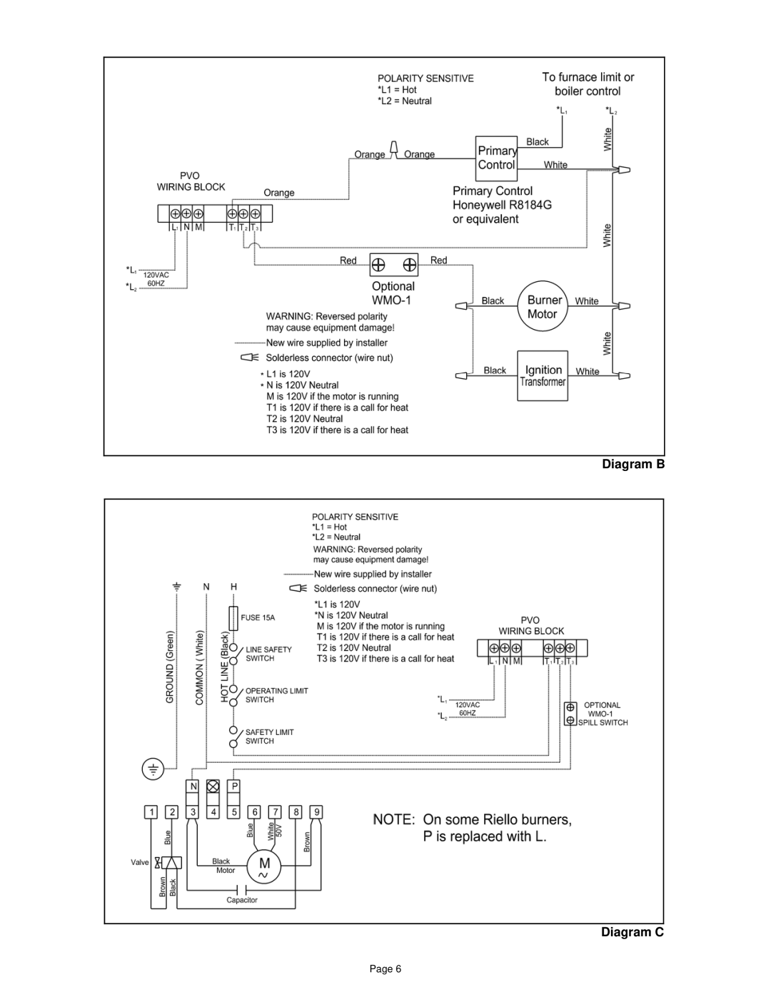
Diagram B Diagram C
Models:
PVO-300
PVO-600
1
6
12
12
Download
12 pages
53.4 Kb
3
4
5
6
7
8
9
10
Install
Parts list
Diagram B Diagram C
Maintenance
Adjustments
Power Venter Sizing
Page 6
Image 6
Diagram B
Diagram C
Page 6
Page 5
Page 7
Page 6
Image 6
Page 5
Page 7
Contents
Typical Venting System Components
Do not Destroy These Instructions Must Remain with Equipment
AMP
Model
Model VAC RPM
Control Kits
BTU/HR Input
Power Venter Sizing
Venter Model NO. and Vent Pipe Diameter
Vent Pipe Fittings Vent Pipe Diameter TEE Elbow Reducer
Installation Safety Instructions
Installation of Power Venter
Diagram B Diagram C
Adjustments
General Installation Inspection
Maintenance
PV Series Power Venter Vertical Venting Option
Description
Replacement Parts List
Installation Information
Venting System Operational Information
Page
46311800 Rev E 11/07
Top
Page
Image
Contents