Blind and shadow sectors
Funnels, stacks, masts, or derricks in the path of antenna may reduce the intensity of the radar beam. If the angle subtended at the scanner is more than a few degrees a blind sector may be produced. Within the blind sector small targets at close range may not be detected while larger targets at much greater ranges may be detected. See Figure
3.6Nautical Chart and Radar Picture
Under normal conditions, a picture which is similar to a nautical chart can be obtained on the radar display. However, a radar can- not:
• | show targets which are below the hori- |
| zon. |
• | show a target which is hidden by a larger |
| one. |
Vessel taller than wharf
Wharf
Wharf
Blind sector (no echo)
Mast, etc. in path of radar beam
Size of blind sector depends on target size and range.
• see around corners (for example, sea- |
wall). |
• distinguish between two targets which are |
very close together, either in range or |
bearing. For example, a vessel towing |
another will probably appear as one ves- |
sel, as both will be covered by the beam |
at the same time. |
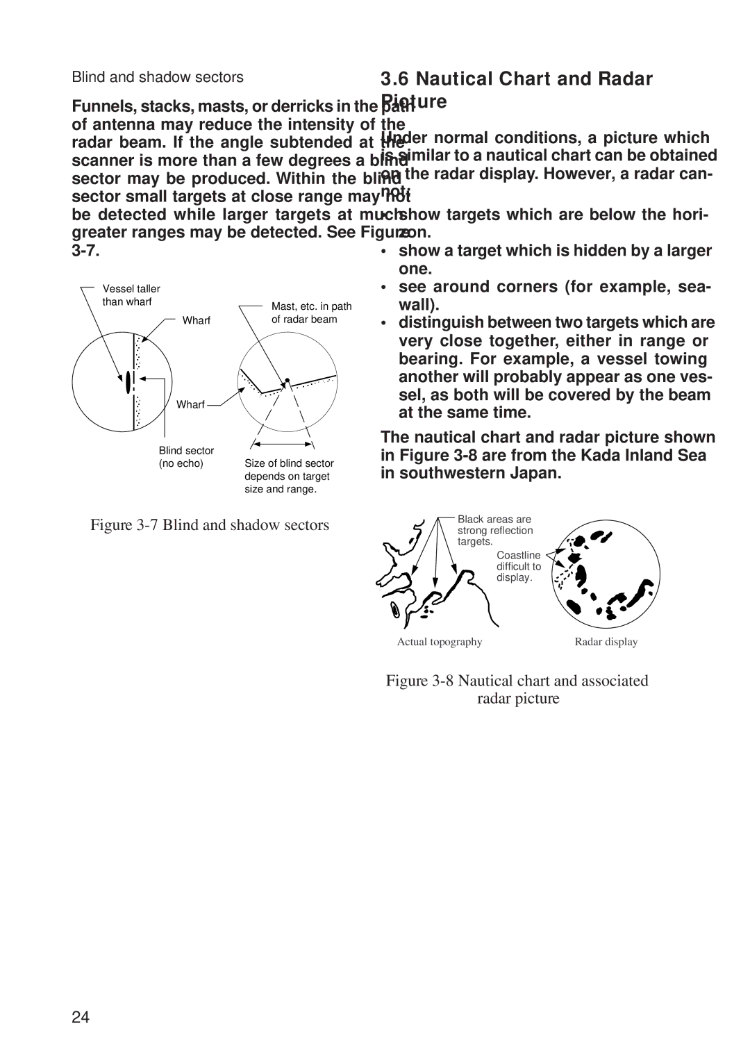
The nautical chart and radar picture shown in Figure
Figure 3-7 Blind and shadow sectors
Black areas are strong reflection targets.
Coastline ![]() difficult to
difficult to ![]() display.
display.
Actual topography | Radar display |
Figure 3-8 Nautical chart and associated
radar picture
24