2.2 Display Indications and Markers
|
|
| Heading (requires |
| ||
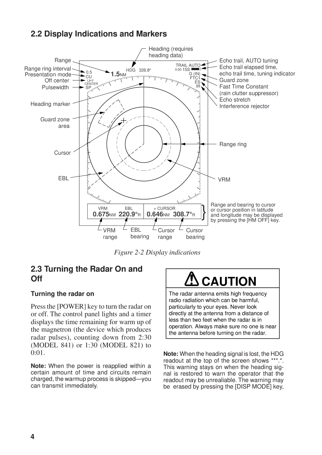
Range |
|
| heading data) | Echo trail, AUTO tuning | ||
|
|
|
| TRAIL AUTO | ||
Range ring interval |
|
|
|
| Echo trail elapsed time, | |
0.5 |
| HDG 326.8° |
| 0:00 15S | ||
Presentation mode | 1.5NM |
| G (IN) | echo trail time, tuning indicator | ||
CU |
| |||||
Off center |
|
|
| FTC1 | Guard zone | |
OFF |
|
|
| ES | ||
Pulsewidth | CENTER |
|
|
| IR | Fast Time Constant |
SP |
|
|
| |||
|
|
|
|
|
| (rain clutter suppressor) |
Heading marker |
|
|
|
|
| Echo stretch |
|
|
|
|
| Interference rejector | |
|
|
|
|
|
| |
Guard zone |
|
|
|
|
|
|
area |
|
|
|
|
|
|
|
|
|
|
|
| Range ring |
Cursor |
|
|
|
|
|
|
EBL |
|
|
|
|
| VRM |
|
| VRM | EBL | + CURSOR | Range and bearing to cursor | |
|
| or cursor position in latitude | ||||
| 0.675NM 220.9°R 0.646NM 308.7°R | } and longitude may be displayed | ||||
|
|
|
|
|
| by pressing the [HM OFF] key. |
|
| VRM | EBL | Cursor | Cursor | |
|
| range | bearing | range | bearing | |
Figure 2-2 Display indications
2.3Turning the Radar On and
Off
Turning the radar on
Press the [POWER] key to turn the radar on or off. The control panel lights and a timer displays the time remaining for warm up of the magnetron (the device which produces radar pulses), counting down from 2:30 (MODEL 841) or 1:30 (MODEL 821) to 0:01.
Note: When the power is reapplied within a certain amount of time and circuits remain charged, the warmup process is
![]() CAUTION
CAUTION
The radar antenna emits high frequency radio radiation which can be harmful, particularly to your eyes. Never look directly at the antenna from a distance of less than two feet when the radar is in operation. Always make sure no one is near the antenna before turning on the radar.
Note: When the heading signal is lost, the HDG readout at the top of the screen shows ***.*. This warning stays on when the heading sig- nal is restored to warn the operator that the readout may be unrealiable. The warning may be erased by pressing the [DISP MODE] key,
4