5. INSTALLATION
This chapter covers installation. Installation mainly consists of the following:
•siting and mounting the display unit and the antenna unit
•connection of the signal cable and the power cable
•establishing the ground
•connecting optional equipment, and
•adjustments.
NOTICE
The installation of this equipment requires certain electrical and mechanical skills. If the owner of the equipment has doubts about his or her technical abilities, we recommend that the equipment be installed by a qualified technician.
5.1 Antenna Unit Installation
Mounting considerations
When selecting a mounting location for the antenna unit keep in mind the following points.
•Install the unit on top of the wheelhouse or on the radar mast on an appropriate platform. It should be placed where there is a good
•Locate the unit at least two meters away from a direction finder antenna to prevent interference to the direction finder.
•In order to minimize the chance of pick- ing up electrical interference, avoid where possible routing the signal cable near other onboard electrical equipment. Also avoid running the cable in parallel with power cables.
•A magnetic compass will be affected if placed too close to the antenna unit. Ob- serve the minimum compass safe dis- tances to prevent deviation of a magnetic compass:
Table 5-1 Compass safe distances
Model | Standard | Steering |
| compass | compass |
|
|
|
821 | 1.7 m | 1.4 m |
|
|
|
841 | 1.4 m | 1.1 m |
|
|
|
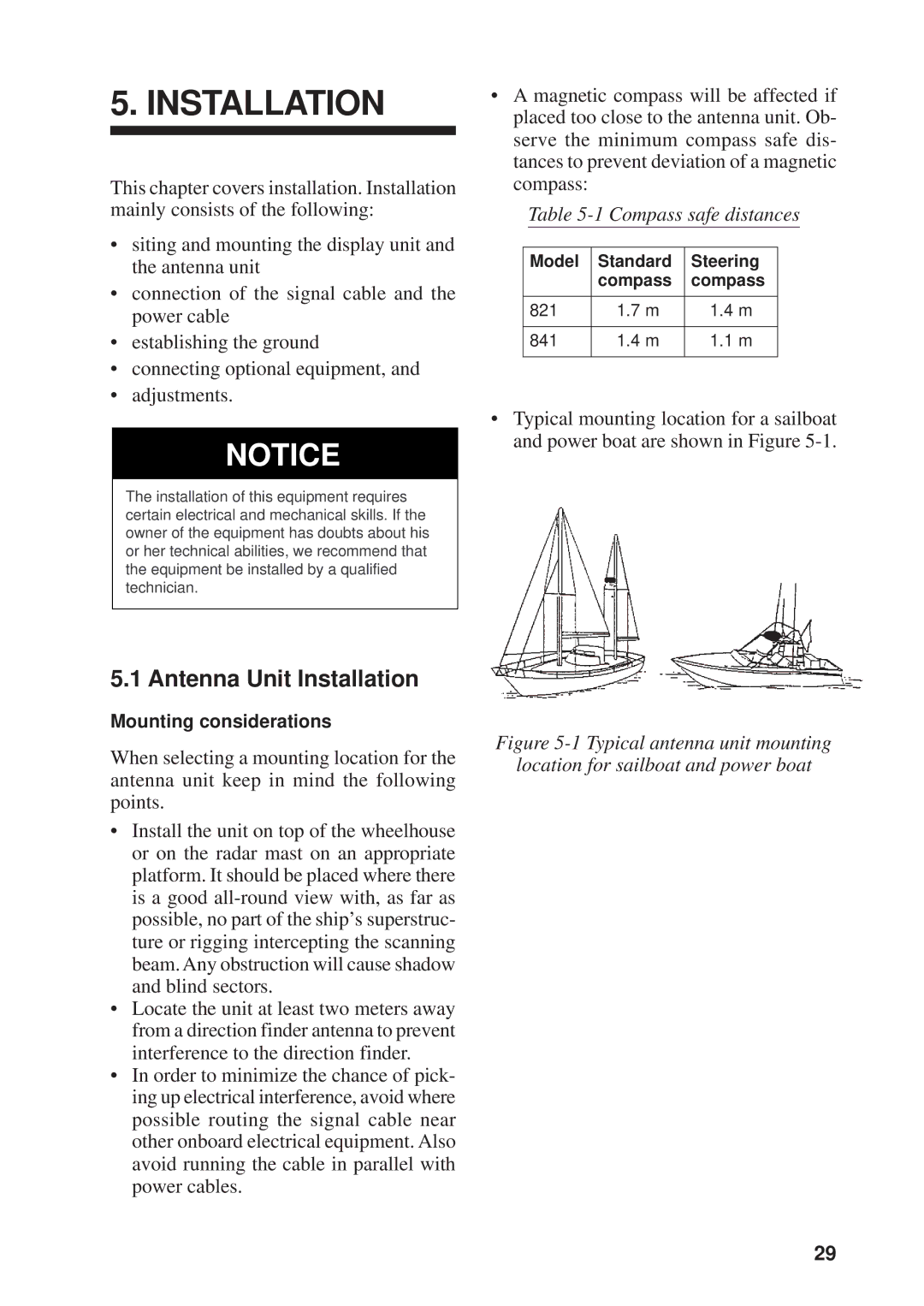
•Typical mounting location for a sailboat and power boat are shown in Figure
Figure 5-1 Typical antenna unit mounting
location for sailboat and power boat
29