Manuals
/
Furuno
/
Marine Equipment
/
Marine RADAR
Furuno
841, 821
manual
Models:
821
841
1
58
64
64
Download
64 pages
26.96 Kb
55
56
57
58
59
60
61
62
Troubleshooting
Specs
Install
Guard Alarm
Maintenance
Configuration
Option connector
Adjusting A/C Rain
Entering Initial Settings
Resolution
Page 58
Image 58
Page 57
Page 59
Page 58
Image 58
Page 57
Page 59
Contents
Marine Radar
First Edition AUG
Ground both the Display Unit and the Antenna Unit
Safety Arrangements
Electrical Shock Hazard
Useable Environment
Table of Contents
Features
Foreword
Transceiver Module contained in radome
SPECIFICATIONS- Model
Antenna Unit
Display Unit
Warm-up time Modulator switching method
Power supply & power consumption
Protection features
Vibration
Ambiont temperature
Receiver front end MIC Michoeave IC Bandwidth 7 MHz Duplexer
Interface Nmea Model 821/841
Page
Configuration
Model 821/841
Principle of Operation
How radar works
Operation
Control Description
Display Indications and Markers
Turning the Radar On Off
Transmitting
Adjusting LCD Backlighting and Display Tone
Adjusting Control Panel Brilliance
Selecting the Range
Adjusting GAIN, STC, A/C Rain and FTC
STC MAN Auto
Adjusting FTC
Tuning the Receiver
Adjusting A/C Rain
How to tune manually
Measuring the Range
Measuring the Bearing
Menu Operation
Target on collision course with your vessel?
Menu description
Selecting the Display Mode
11 Display modes
Window Display
Selecting the Presentation Mode
CU course-up
Guard Alarm
WPT-UP waypoint-up
Suppressing Radar Interference
Guard
Off Centering the Display
Suppressing Noise Interference
Selecting Pulselength
Echo Trails
Navigation Data Display
Echo Stretch magnifying long range echoes
Press the Menu key Select Nav Data and press the ENT key
Selecting Bearing Reference
Selecting Unit of Measurement for Range
Watchman
Deselecting Ranges
Erasing the Heading Marker
Displaying Navigation Data During Stand-by
Outputting Cursor Position to Navigator
Visual Alarm Indications
Displaying Cursor Position, Range and Bearing to Cursor
Target Properties and Radar Wave Reflection
Interpreting the Display
Radar Wave and Radar Horizon
Super-refraction
Range Resolution
Bearing Resolution
False Echoes
Multiple echoes
Nautical Chart and Radar Picture
Blind and shadow sectors
Forming any maintenance or
Maintenance & Troubleshooting
Safety Information
Troubleshooting procedure
Preventative Maintenance
Replacing the Fuse
Troubleshooting
Troubleshooting table
Self Test
Self Test
Installation
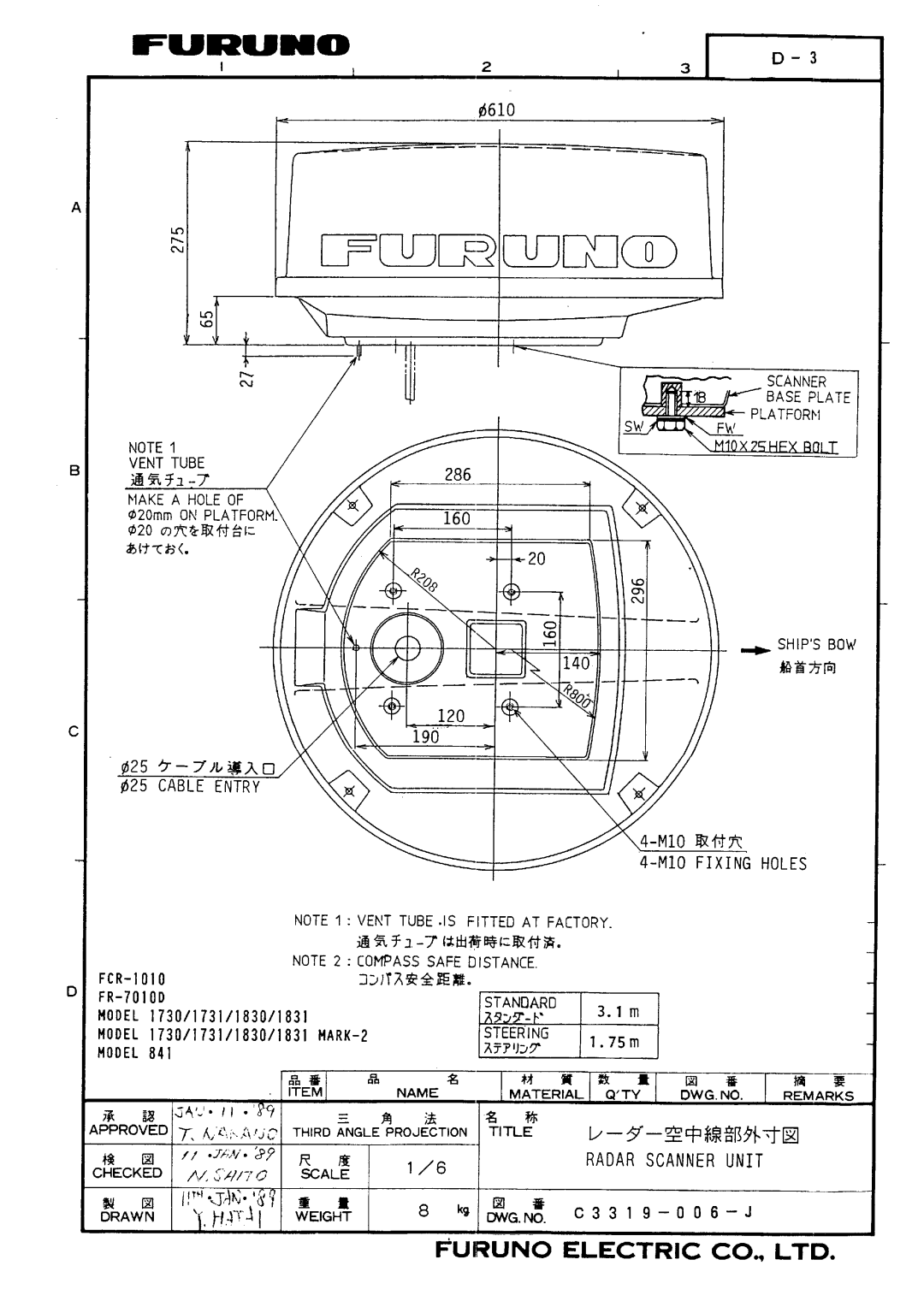
Antenna Unit Installation
Mounting platform
Removing packing materials
Vent tube
How to fasten the radome base To the mounting platform
Ships bow
Removing packing materials
10 Antenna unit Model 841, inside view, shield cover removed
12 Optional mounting bracket installation for sailboat
Display Unit Installation
13 How to mount the display unit
14 Display unit, rear view
Option connector
Procedure
Installation Check List
Initial Adjustment of Picture
Displaying the Installation Menus
Entering Initial Settings
Relative Bearing Alignment
Closing the Installation Menus
Sweep Timing
Signal cable connection
Page
Page
Page
Page
Page
Page
Page
Top
Page
Image
Contents