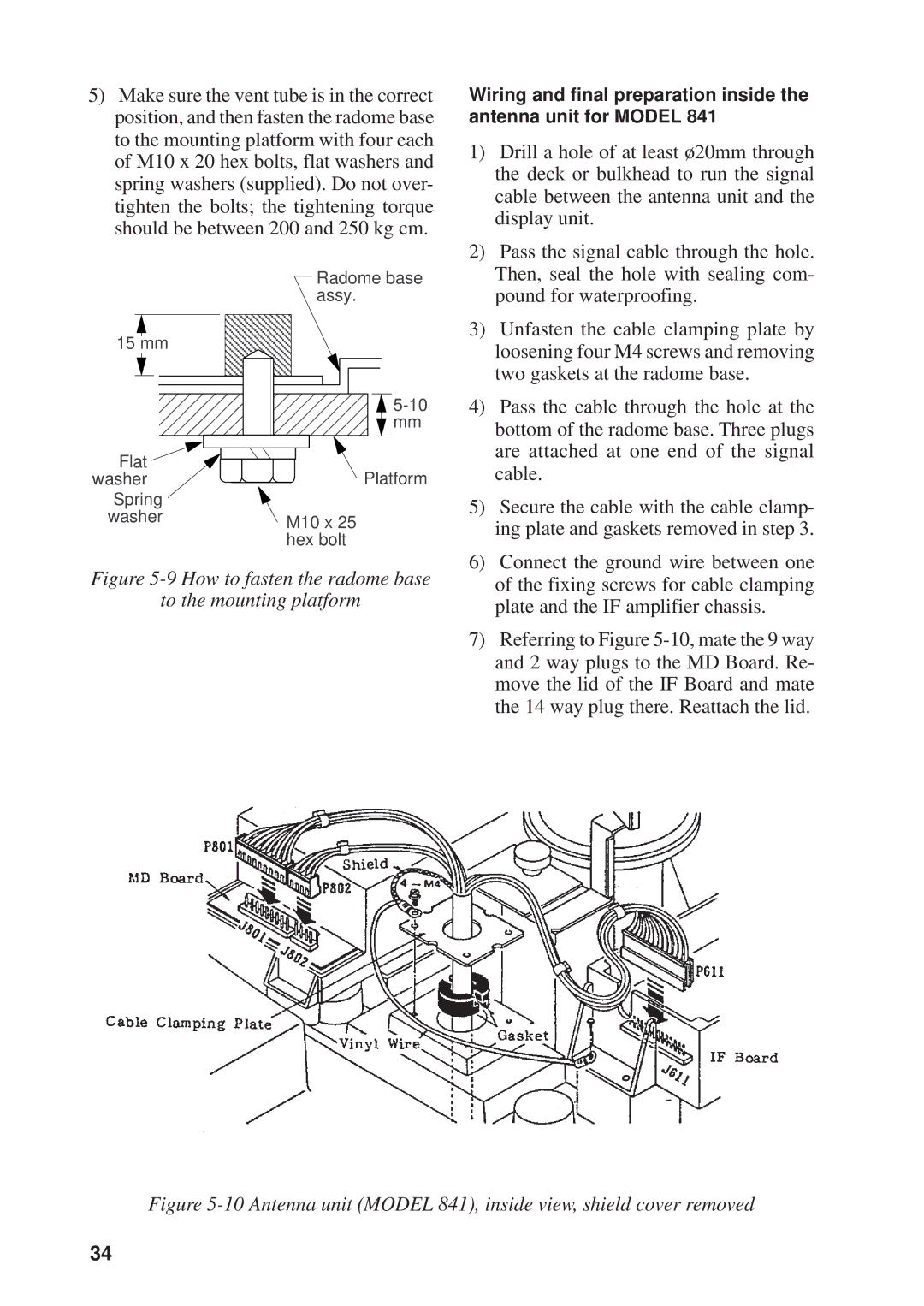
5)Make sure the vent tube is in the correct position, and then fasten the radome base to the mounting platform with four each of M10 x 20 hex bolts, flat washers and spring washers (supplied). Do not over- tighten the bolts; the tightening torque should be between 200 and 250 kg cm.
Radome base assy.
15 mm
![]()
![]() mm
mm
Flat | Platform |
washer |
Spring
washerM10 x 25 hex bolt
Figure 5-9 How to fasten the radome base
to the mounting platform
Wiring and final preparation inside the antenna unit for MODEL 841
1)Drill a hole of at least ø20mm through the deck or bulkhead to run the signal cable between the antenna unit and the display unit.
2)Pass the signal cable through the hole. Then, seal the hole with sealing com- pound for waterproofing.
3)Unfasten the cable clamping plate by loosening four M4 screws and removing two gaskets at the radome base.
4)Pass the cable through the hole at the bottom of the radome base. Three plugs are attached at one end of the signal cable.
5)Secure the cable with the cable clamp- ing plate and gaskets removed in step 3.
6)Connect the ground wire between one of the fixing screws for cable clamping plate and the IF amplifier chassis.
7)Referring to Figure
Figure 5-10 Antenna unit (MODEL 841), inside view, shield cover removed
34
