|
| |
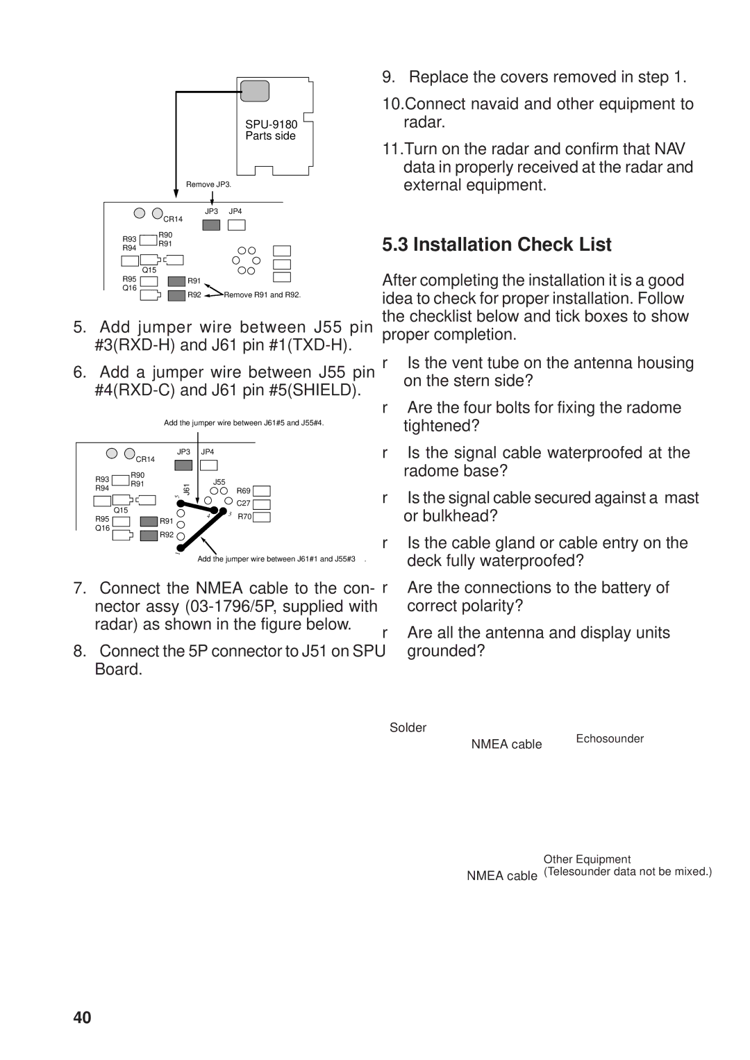
|
| Parts side |
| Remove JP3. | |
| JP3 | JP4 |
| CR14 |
|
R93 | R90 |
|
R91 |
| |
R94 |
| |
|
| |
R95 | Q15 |
|
R91 |
| |
Q16 | R92 | Remove R91 and R92. |
| ||
5.Add jumper wire between J55 pin
6.Add a jumper wire between J55 pin
Add the jumper wire between J61#5 and J55#4.
| JP3 | JP4 |
|
| |
| CR14 |
|
|
|
|
R93 | R90 |
| J55 |
|
|
R91 | J61 |
|
| ||
R94 |
| R69 | |||
5 |
|
| |||
|
|
|
| ||
|
|
|
|
| |
| Q15 |
|
|
| C27 |
R95 |
| 4 | 3 | R70 | |
R91 |
| ||||
|
|
|
| ||
Q16 | R92 |
|
|
|
|
|
|
|
|
| |
| 1 |
|
|
|
|
Add the jumper wire between J61#1 and J55#3.
7.Connect the NMEA cable to the con- nector assy
8.Connect the 5P connector to J51 on SPU
Board.
9. Replace the covers removed in step 1.
10.Connect navaid and other equipment to radar.
11.Turn on the radar and confirm that NAV data in properly received at the radar and external equipment.
5.3 Installation Check List
After completing the installation it is a good idea to check for proper installation. Follow the checklist below and tick boxes to show proper completion.
❒Is the vent tube on the antenna housing on the stern side?
❒Are the four bolts for fixing the radome tightened?
❒Is the signal cable waterproofed at the radome base?
❒Is the signal cable secured against a mast or bulkhead?
❒Is the cable gland or cable entry on the deck fully waterproofed?
❒Are the connections to the battery of correct polarity?
❒Are all the antenna and display units grounded?
Solder
NMEA cab | le | Echosounder |
|
Other Equipment
NMEA cable (Telesounder data not be mixed.)
40