2.21 Echo Trails
You can show the trails of targets in after- glow. This function is useful for alerting you to possible collision situations.
Starting echo trail
Press the [TRAIL] key to start the echo trail function. Afterglow starts extending from targets and "TRAIL" and the echo trail time appear at the top
Note: If the range is changed, trails are painted anew with the newly selected range.
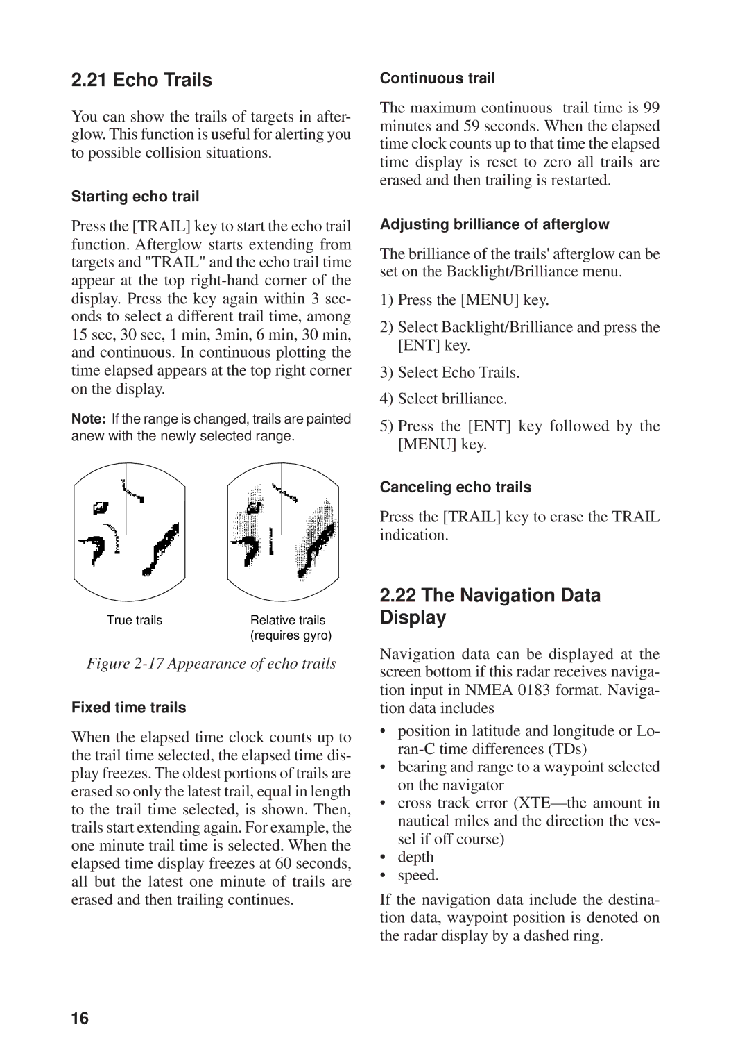
True trails | Relative trails |
| (requires gyro) |
Figure 2-17 Appearance of echo trails
Fixed time trails
When the elapsed time clock counts up to the trail time selected, the elapsed time dis- play freezes. The oldest portions of trails are erased so only the latest trail, equal in length to the trail time selected, is shown. Then, trails start extending again. For example, the one minute trail time is selected. When the elapsed time display freezes at 60 seconds, all but the latest one minute of trails are erased and then trailing continues.
Continuous trail
The maximum continuous trail time is 99 minutes and 59 seconds. When the elapsed time clock counts up to that time the elapsed time display is reset to zero all trails are erased and then trailing is restarted.
Adjusting brilliance of afterglow
The brilliance of the trails' afterglow can be set on the Backlight/Brilliance menu.
1)Press the [MENU] key.
2)Select Backlight/Brilliance and press the [ENT] key.
3)Select Echo Trails.
4)Select brilliance.
5)Press the [ENT] key followed by the [MENU] key.
Canceling echo trails
Press the [TRAIL] key to erase the TRAIL indication.
2.22The Navigation Data Display
Navigation data can be displayed at the screen bottom if this radar receives naviga- tion input in NMEA 0183 format. Naviga- tion data includes
•position in latitude and longitude or Lo-
•bearing and range to a waypoint selected on the navigator
•cross track error
•depth
•speed.
If the navigation data include the destina- tion data, waypoint position is denoted on the radar display by a dashed ring.
16