FTLF1217P2xTL Pluggable SFP Product Specification – September 2008
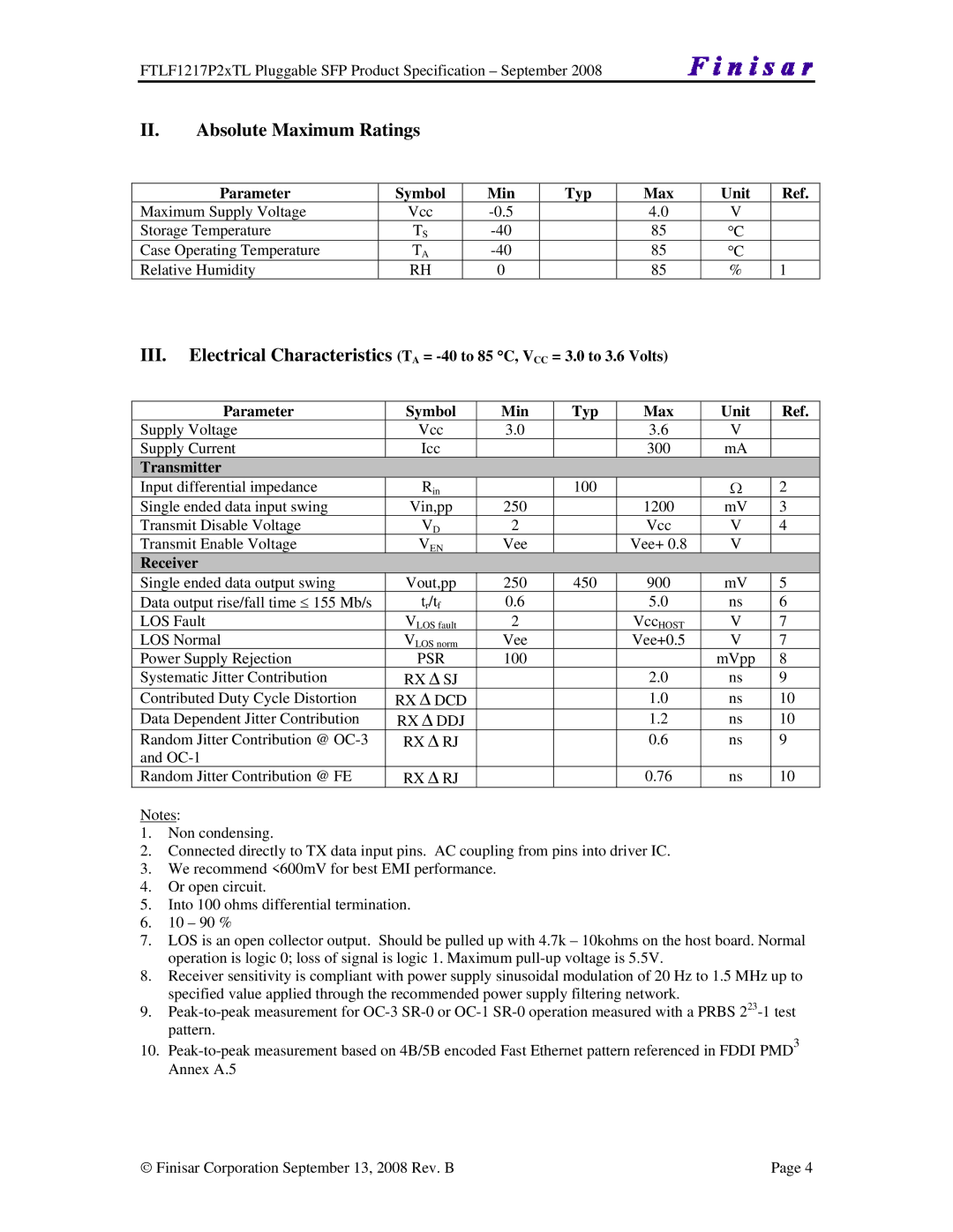
II.Absolute Maximum Ratings
Parameter | Symbol | Min |
Maximum Supply Voltage | Vcc | |
Storage Temperature | TS | |
Case Operating Temperature | TA | |
Relative Humidity | RH | 0 |
Typ
Max | Unit | Ref. |
4.0V
85°C
85°C
85 | % 1 |
III.Electrical Characteristics (TA =
Parameter | Symbol | Min | Typ | Max | Unit | Ref. |
Supply Voltage | Vcc | 3.0 |
| 3.6 | V |
|
Supply Current | Icc |
|
| 300 | mA |
|
Transmitter |
|
|
|
|
|
|
Input differential impedance | Rin |
| 100 |
| Ω | 2 |
Single ended data input swing | Vin,pp | 250 |
| 1200 | mV | 3 |
Transmit Disable Voltage | VD | 2 |
| Vcc | V | 4 |
Transmit Enable Voltage | VEN | Vee |
| Vee+ 0.8 | V |
|
Receiver |
|
|
|
|
|
|
Single ended data output swing | Vout,pp | 250 | 450 | 900 | mV | 5 |
Data output rise/fall time ≤ 155 Mb/s | tr/tf | 0.6 |
| 5.0 | ns | 6 |
LOS Fault | VLOS fault | 2 |
| VccHOST | V | 7 |
LOS Normal | VLOS norm | Vee |
| Vee+0.5 | V | 7 |
Power Supply Rejection | PSR | 100 |
|
| mVpp | 8 |
Systematic Jitter Contribution | RX Δ SJ |
|
| 2.0 | ns | 9 |
Contributed Duty Cycle Distortion | RX Δ DCD |
|
| 1.0 | ns | 10 |
Data Dependent Jitter Contribution | RX Δ DDJ |
|
| 1.2 | ns | 10 |
Random Jitter Contribution @ | RX Δ RJ |
|
| 0.6 | ns | 9 |
and |
|
|
|
|
|
|
Random Jitter Contribution @ FE | RX Δ RJ |
|
| 0.76 | ns | 10 |
Notes:
1.Non condensing.
2.Connected directly to TX data input pins. AC coupling from pins into driver IC.
3.We recommend <600mV for best EMI performance.
4.Or open circuit.
5.Into 100 ohms differential termination.
6.10 – 90 %
7.LOS is an open collector output. Should be pulled up with 4.7k – 10kohms on the host board. Normal operation is logic 0; loss of signal is logic 1. Maximum
8.Receiver sensitivity is compliant with power supply sinusoidal modulation of 20 Hz to 1.5 MHz up to specified value applied through the recommended power supply filtering network.
9.
10.
♥ Finisar Corporation September 13, 2008 Rev. B | Page 4 |