FOLLOW THESE INSTALLATION STEPS

The basic installation of this Heat Alarm is the similar whether you want to install one Heat Alarm, or interconnect more than one Heat Alarm. If you are interconnecting more than one Heat Alarm, you MUST read “Special Requirements for Interconnected Heat Alarms” below before you begin installation.

ELECTRICAL SHOCK HAZARD. Turn off power to the area where you will install this unit at the circuit breaker or fuse box before beginning installation. Failure to turn off the power before installation may result in serious electrical shock, injury or death.

1.Remove the mounting bracket from the base. Position the screw slots on the mounting bracket over the screws in the junction box. Tighten the screws.

2.Using wire nuts, connect the power connector to the household wiring.

Improper wiring of the power connector or the wiring leading to the power connector will cause damage to the Alarm and may lead to a non-functioning Alarm.

STAND-ALONE ALARM ONLY:

Connect the white wire on the power connector to the neutral wire in the junction box.

Connect the black wire on the power connector to the hot wire in the junction box.

Tuck the orange wire inside the junction box. It is used for interconnect only.

INTERCONNECTED UNITS ONLY:

Strip off about 1/2” (12 mm) of the plastic coating on the orange wire on the power connector.

Connect the white wire on the power connector to the neutral wire in the junction box.

Connect the black wire on the power connector to the hot wire in the junction box.

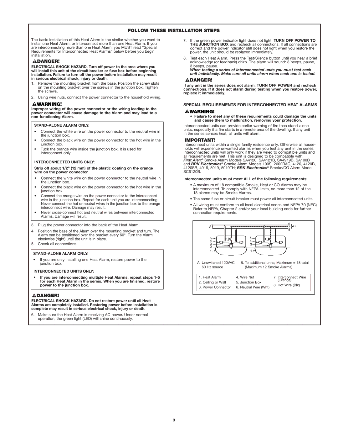
Connect the orange wire on the power connector to the interconnect wire in the junction box. Repeat for each unit you are interconnecting. Never connect the hot or neutral wires in the junction box to the orange interconnect wire. Damage may result.

Never cross-connect hot and neutral wires between interconnected Alarms. Damage will result.

3.Plug the power connector into the back of the Heat Alarm.

4.Position the base of the Alarm over the mounting bracket and turn. The Alarm can be positioned over the bracket every 60°. Turn the Alarm clockwise (right) until the unit is in place.

5.Check all connections.

STAND-ALONE ALARM ONLY:

If you are only installing one Heat Alarm, restore power to the junction box.

INTERCONNECTED UNITS ONLY:

If you are interconnecting multiple Heat Alarms, repeat steps 1-5 for each Heat Alarm in the series. When you are finished, restore power to the junction box.

ELECTRICAL SHOCK HAZARD. Do not restore power until all Heat Alarms are completely installed. Restoring power before installation is complete may result in serious electrical shock, injury or death.

6.Make sure the Heat Alarm is receiving AC power. Under normal operation, the green light (LED) will shine continuously.

7.If the green power indicator light does not light, TURN OFF POWER TO THE JUNCTION BOX and recheck all connections. If all connections are correct and the power indicator still does not light when you restore the power, the unit should be replaced immediately.

8.Test each Heat Alarm. Press the Test/Silence button until you hear a brief acknowledge (or feedback) chirp. The alarm will sound: 3 beeps, pause, 3 beeps, pause.

When testing a series of interconnected units you must test each unit individually. Make sure all units alarm when each one is tested.

If any unit in the series does not alarm, TURN OFF POWER and recheck connections. If it does not alarm during testing when you restore power, replace it immediately.

SPECIAL REQUIREMENTS FOR INTERCONNECTED HEAT ALARMS

Failure to meet any of these requirements could damage the units and cause them to malfunction, removing your protection.

Interconnected units can provide earlier warning of fire than stand-alone units, especially if a fire starts in a remote area of the dwelling. If any unit in the series senses heat, all units will alarm.

Interconnect units within a single family residence only. Otherwise all house- holds will experience unwanted alarms when you test any unit in the series. Interconnected units will only work if they are wired to compatible units and all requirements are met. This unit is designed to be compatible with:

First Alert® Smoke Alarm Models SA4120, SA4121B, SA4919B, SA100B and BRK Electronics® Smoke Alarm Models 100S, 2002RAC, 4120, 4120B, 4120SB, 4919, 5919, 5919TH; BRK Electronics® Smoke/CO Alarm Model SC6120B.

Interconnected units must meet ALL of the following requirements:

A maximum of 18 compatible Smoke, Heat or CO Alarms may be interconnected. To comply with NFPA limits, no more than 12 of the 18 alarms may be Smoke Alarms.

The same fuse or circuit breaker must power all interconnected units.

All wiring must conform to all local electrical codes and NFPA 70 (NEC). Refer to NFPA, Chapter 2 and/or your local building code for further connection requirements.

6

A} 7 } B 8

5

5

4

4

3

3

2


1

1

A. Unswitched 120VAC B. To additional units; Maximum = 18 total


60 Hz source


(Maximum 12 Smoke Alarms)


1.

Heat Alarm

4.

Wire Nut

7.

Interconnect Wire

2.

Ceiling or Wall

5.

Junction Box


(Orange)

8.

Hot Wire (Blk)

3.

Power Connector

6.

Neutral Wire (Wht)


3

Page 3
Image 3
First Alert HD6135FB user manual Follow These Installation Steps, Special Requirements for Interconnected Heat Alarms

HD6135FB specifications

The First Alert HD6135FB is a state-of-the-art smoke and carbon monoxide alarm that combines advanced technology with user-friendly features. Designed to provide peace of mind for homeowners, the HD6135FB offers reliable performance and comprehensive safety monitoring.

One of its main features is the photoelectric sensor. This technology helps to reduce false alarms by quickly detecting smoldering fires that produce smoke without large flames. By distinguishing between different types of smoke, the HD6135FB minimizes unnecessary disruptions while still responding rapidly to genuine fire threats. Additionally, the unit includes an electrochemical CO sensor, which is highly sensitive in detecting carbon monoxide leaks, making it essential for safeguarding against this odorless and potentially deadly gas.

User convenience is prioritized in this model, as illustrated by its intuitive design. The First Alert HD6135FB comes equipped with a voice alarm feature, providing clear spoken warnings to alert homeowners to the specific danger—whether smoke or carbon monoxide. This audible notification ensures that residents can quickly respond to potential threats.

The device also boasts a battery-operated design, allowing for easy installation without the need for hardwiring. It is powered by lithium batteries, known for their long life, which reduces the frequency of battery changes. Additionally, the low battery chirp alerts users when it's time to replace the batteries, enhancing convenience and safety.

To make maintenance straightforward, this smoke and CO alarm includes a test/silence button. Homeowners can easily test the functionality of the device and silence false alarms with a single touch. Furthermore, the HD6135FB features a snap-on cover that streamlines battery replacements, minimizing the hassle associated with maintenance.

With its sleek design and compact profile, the First Alert HD6135FB is suitable for various home environments, easily blending with any decor. It is also equipped with an indicator light that provides a visual cue of the unit's operating status, ensuring residents are aware of its functionality at all times.

Overall, the First Alert HD6135FB represents a blend of cutting-edge technology, thoughtful design, and essential safety features, making it an excellent choice for homeowners committed to maintaining a safe living environment. Its integration of photoelectric and electrochemical sensors, along with user-friendly functionalities, establishes it as a reliable guardian against two of the most significant hazards in residential areas: fire and carbon monoxide.