Dimensions
A
B
C
F J
E
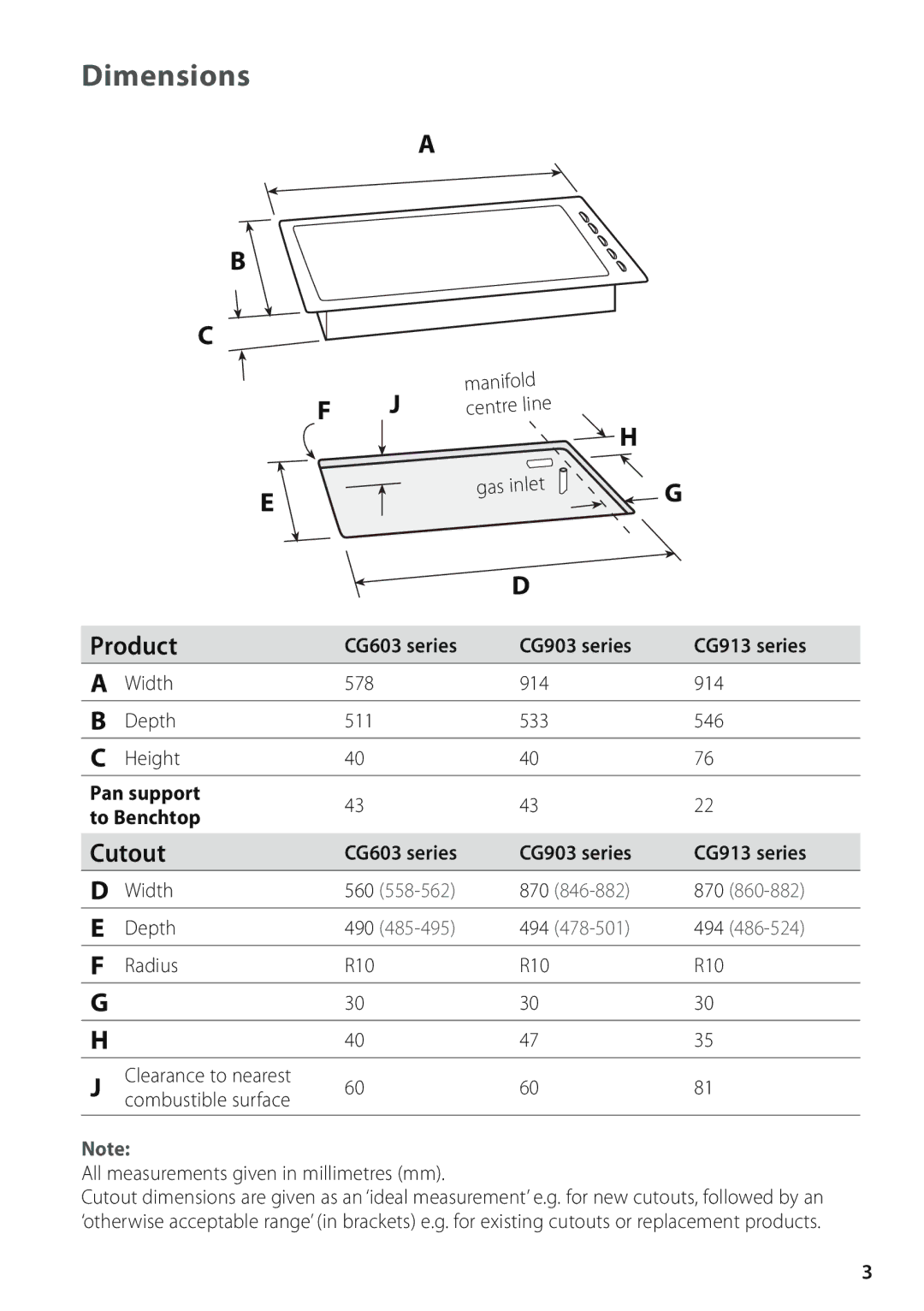
manifold | |
centre | line |
| |
gas inlet | |
D
![]() H
H
![]() G
G
Product | CG603 series | CG903 series | CG913 series | ||
A Width | 578 | 914 | 914 | ||
B | Depth | 511 | 533 | 546 | |
C | Height | 40 | 40 | 76 | |
Pan support | 43 | 43 | 22 | ||
to Benchtop | |||||
|
|
| |||
Cutout | CG603 series | CG903 series | CG913 series | ||
D Width | 560 | 870 | 870 | ||
E | Depth | 490 | 494 | 494 | |
F | Radius | R10 | R10 | R10 | |
G |
| 30 | 30 | 30 | |
H |
| 40 | 47 | 35 | |
J | Clearance to nearest | 60 | 60 | 81 | |
combustible surface | |||||
|
|
| |||
|
|
|
|
| |
Note:
All measurements given in millimetres (mm).
Cutout dimensions are given as an ‘ideal measurement’ e.g. for new cutouts, followed by an ‘otherwise acceptable range’ (in brackets) e.g. for existing cutouts or replacement products.
3