(1,2)
RECOMMENDED METHOD - SECURE WITHOUT
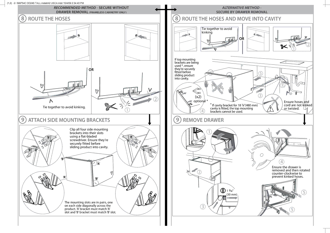
DRAWER REMOVAL (FRAMELESS CABINETRY ONLY)
8ROUTE THE HOSES
ALTERNATIVE METHOD -
SECURE BY DRAWER REMOVAL
8ROUTE THE HOSES AND MOVE INTO CAVITY
OR
Tie together to avoid kinking
![]()
![]()
![]()
![]()
![]() OR
OR
If top mounting |
| |
brackets are being |
| |
used *, ensure |
| |
they’re securely |
| |
fitted before | 5 | |
sliding product | ||
| ||
into cavity. |
|
2
1
3
Tie together to avoid kinking.
2
1
(x2) | 3 |
optional * | * If cavity bracket for 18 7⁄8”(480 mm) |
| |
4 | cavity is fitted, the top mounting |
brackets cannot be used. |
Ensure hoses and cord are not kinked or twisted. ![]()
9ATTACH SIDE MOUNTING BRACKETS
9REMOVE DRAWER

 ‘B’
‘B’


![]()
![]()
![]() ‘B’
‘B’![]()
![]()
![]()
![]()
![]()
![]()
Clip all four side mounting brackets into their slots using a
‘B’ ![]()
‘A’
![]()
![]() ‘A’
‘A’![]()
![]()
![]()
![]()
![]()
![]()
![]()

![]()
![]() ‘A’
‘A’![]()
![]()
4
Ensure the drawer is removed and then rotated
|
| ‘A’ | ‘B’ |
|
|
|
|
| |
| ‘A’ |
|
| ‘B’ |
|
|
|
| |
‘A’ |
| The mounting slots are in pairs, one | ‘B’ | |
|
| |||
|
|
| ||
|
| on each side diagonally across the |
| |
|
| product. ‘A’ bracket must match ‘A’ |
| |
|
| slot and ‘B’ bracket must match ‘B’ slot. |
| |
1
2
![]()
![]() 1 3⁄16”
1 3⁄16”
(30 mm)
3
prevent kinked hoses.
5
5