Page
92B/96B/99B/105B
Table of Contents
Using the Dual Display Mode Functions
Using in Scope Mode
User Maintenance
Using Additional Capabilities
Measuring Examples
Appendixes
About this Manual
Unpacking the Scopemeter Test Tool KIT
Index
Safety
Safety Precautions
Common Ground Connections
Isolating from Earth Ground
Making Isolated Measurements
Isolating from Input to Input
Fluke 92B/96B/99B/105B
Statement of Conformity
Input Connections for High Frequency Electronic Measurement
Dual Input Connections with
Introducing your ScopeMeter Test Tool
Scope Capabilities
Scopemeter Test Tool Features
ScopeMeter Features
Digital MultiMeter Capabilities
Using the Holster and the Tilt Stand
Multiposition Stand
Powering the Scopemeter Test Tool
Minimizing Signal Noise
Charging the Battery
Saving Battery Life
Common Ground, Inputs a B
Looking AT ALL Measurement Connections
Input/Output Terminal Ratings
Reading the Display
RS-232 Optical Interface Connection
Reading a Scope Display
Reading a Dual Display
Reading a Window Display
Using the Keys
Keypad
Basic Navigation
Stepping Through a Window
Sequence to Go Through a Window
Using ON-LINE Information
Using On-Line Information
Getting Started
Page
Adjusting the Contrast
Adjusting the Display
Using the Backlight
POWER-ON Configurations
Selecting the Probe Type
Performing AN Easy Setup
Power-on/save memory
Quick Measurements Demonstration
Choose another measurement. For now, highlight rise time
Mode now ?
Performing Some Meter Operations
Submenu identifiers
Performing Some Scope Operations
Readable display of the waveform
Performing Some Scope Operations
Making Measurements
Making Connections
92B/96B/99B/105B
Using the Measurement Functions
Measure Menu
Measurement results in Dual Display mode Scope mode
Making Measurements
Page
Meter mode
Meter Measure the frequency of the input signal
Scope Measure the frequency of the waveform
Rise Time Measurement
Using a Shortcut to Most Commonly Measurements
Measuring Functions not Available from the Measure Menu
Ordering Measurement Readings
Additional measurements for Meter and EXT.mV modes
Additional measurements for the Scope mode
Measurements MAP
Time Measurements
Ampere Measurements
Using the Dual Display Mode Functions
Making Connections
Selecting a Main Mode
Main menu
Page
Page
Page
Selecting Ranges MANUAL/AUTO Range
Holding a Stable Measurement Touch HOLD
Touch Hold function is not available in Min Max
Displaying Minimum Maximum Readings with Related Trendplot
Generating a Min Max TrendPlot with the Fluke 92B
Looking at the Graphical Plot TrendPlot
Page
Enabling and Disabling the Change Alert Function
Selecting the Scopemeter KEY Submenu
Changing the Refresh Rate of the Display
Changing the number of readings
Taking Relative Readings Scaling
Readings Relative to a Reference Point Zero ∆
Readings as a Percent Change from Reference Point Zero %∆
Readings Displayed as a Percent of Scale 0%-100%
Scaling in Combination with Min Max Trendplot Recording
Stop Scaling
Using in Scope Mode
Using the MIN MAX Envelope
To prevent electric shock and personal injury, Mini Test
Scope Connections
Selecting the Input
Making AN Easy Setup
Controlling Inputs a and B
Selecting the Input Coupling
Capturing Glitches
Adjusting the Amplitude
Reversing the Polarity of the Displayed Waveform
Adjusting the Time Base
Time Base and Amplitude Adjustment
Positioning the Waveform on Display
Considerable flexibility is offered in moving the traces
Acquiring Waveforms
Roll Mode
Choosing Recurrent or Single Acquisition
Zoom in a Waveform
Selecting the Scope Submenu
Capturing 10 or 20 Divisions
Smoothing the Waveform Average
Average Waveforms OFF changes to Average
Trigger Basics
Triggering
20 ms/DIV Triga
Defining the Trace Start
Selecting a Trigger Source
Selecting a Trigger Slope
Choosing a Trigger Delay
Adjusting the Trigger Level
Automatic Trigger Level
TV Triggering Function
Overview of the TV Trigger functions
13. TV system and trigger function indicator
Selecting TV System and Scan Rate
Using the Lines Trigger Function
Using the Frame Trigger Function
Using the Select Line Trigger Function
14. Select Line menu
Using the 4-field Sequence Function
15. Measuring a color burst with 4-FIELD
Using the MIN MAX Envelope Function Fluke 92B
Using the Min Max Envelope Function
Using the Scope Record and MIN MAX Envelope Functions
Fluke 96B, 99B, or 105B
Using the ScopeRecord function
Examining the ScopeRecord
17. Examine menu
Using the Min Max Envelope Function
Making Combinations with Input a Input B
Displaying Multiple Waveforms
Selecting a Dot Size
Adjusting the Trace Quality
Adapting the Display
Selecting a Display Grid
Page
Using Additional Capabilities
Making Measurements Using Cursors
Using the Markers
Zero ∆
Adding a Cursor Main Reading
Cursor Main Readings List Box
Page
Deleting Memories
Delete Memory List Box
Saving a Screen
Saving a Setup
Saving to Memory
Saving Acquired Waveforms
Copying Waveforms or Settings
Recalling from Memory 92B
Recalling a Waveform
Recalling a Setup Configuration
Scaling the Display
Using Waveform Math Functions
Choosing a Math Operation
Page
Page
Setting Print Parameters
Using a Printer
Connecting to a Printer
Selecting Printer Types
Page
Printing Grey in White or Black
Sending to a Printer
Using the Waveform Generator
Testing Components 92B 96B
Page
Setting the Date and Time
Setting the Time
Changing the Reset Configurations
Setting the Date
12. Reset Menu Window
Using Manual Override
Altering the Continuous Auto SET Configuration
Changing Continuous Auto Set Options
Page
Measuring Examples
Measuring Temperature
RED DOT
Temperature Measurement with Trend Plot
Measuring Current
30V RMS or 42V DC
‘ ¹ ’
Current Measurement in Scope Mode
Measuring Power with Math Function
Power Measurement Setup
’ ¹
Measuring THREE-PHASE on a Dual Input
Testing a Three-Phase System
Connecting the Wires
10. Phase Measurements
Measuring Phase Using the Cursors
12. Phase Measurement with Markers
Measuring Pulse Response of AN Amplifier
13. Measuring the rise time of a pulse
14. Rise Time Measurement with markers
User Maintenance
Cleaning
Keeping Batteries in Optimal Condition
Replacing and Disposing Batteries
Battery Replacement
Calibrating the Probes
Replacing Fuses
Input a Probe Calibration
Adjusting the Probe
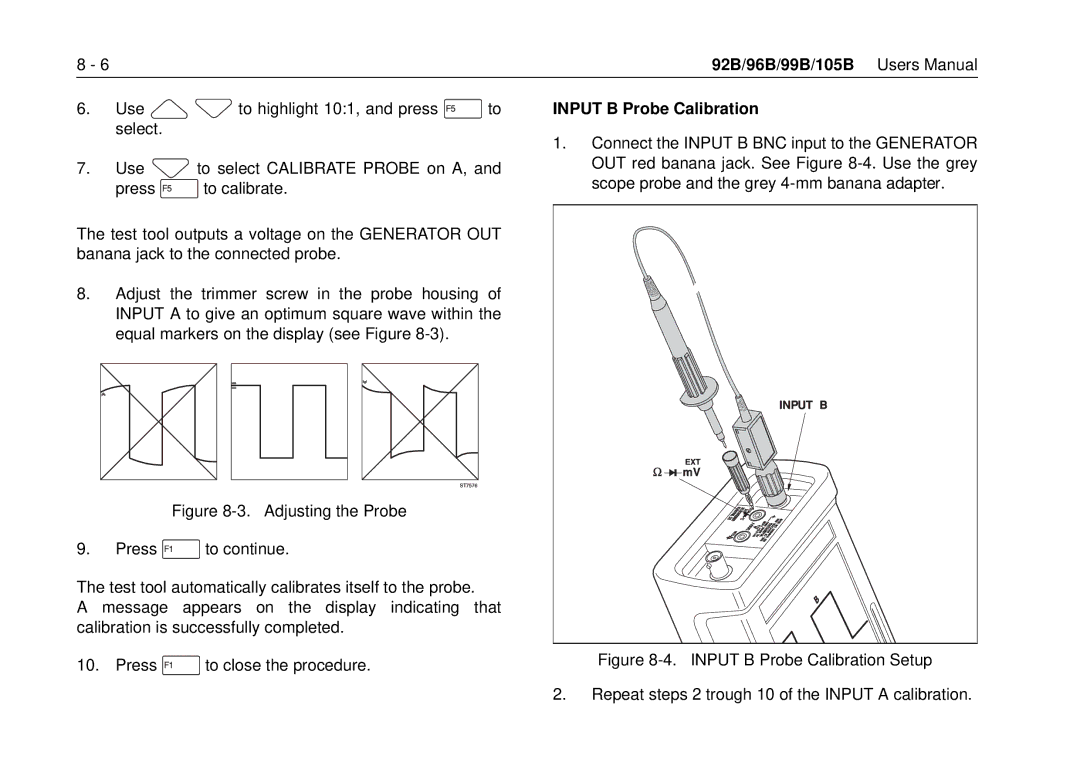
Input B Probe Calibration
Appendixes
Specifications
Measure Menu
Zoom
Meter Mode
Mode
Probe Calibrator
General Specifications
Environmental
Susceptibility disturbance less than 10% of full scale
Susceptibility disturbance less than 10 % of full scale
Accessory Information
Parts and Accessories
Description Model Part Number Remark
Description Model Part Number Remark
Description Model Part Number Remark
PM8907 Information
92B/96B/99B/105B
Warranty and Service Centers
Service Centers
Terminology
DB See decibel DC See Direct Current
GND See Ground level
Page
Page
Page
Symbol
Cursors, 6-2
Delay
Hold Holster, 1-3
Parts
Rise Time, 3-8, 6-5, 7-15 Roll, 5-6 RPM
Smooth, 4-13
V1 left, 3-11 V2 right, 3-11