99B, 105B specifications
The Fluke 105B and Fluke 99B are highly regarded oscilloscopes that offer a blend of performance, portability, and user-friendly features, making them ideal tools for both professionals and enthusiasts in the electronics field. These oscilloscopes exemplify Fluke's commitment to quality and precision in electrical testing and diagnostics.One of the standout features of the Fluke 105B and 99B is their exceptional bandwidth and sampling rates. The 105B typically boasts a bandwidth of up to 100 MHz, while the 99B offers similar specifications. This ensures that both models can accurately capture fast signal changes and perform detailed analysis of electrical waveforms, making them suitable for a wide range of applications in the industry.
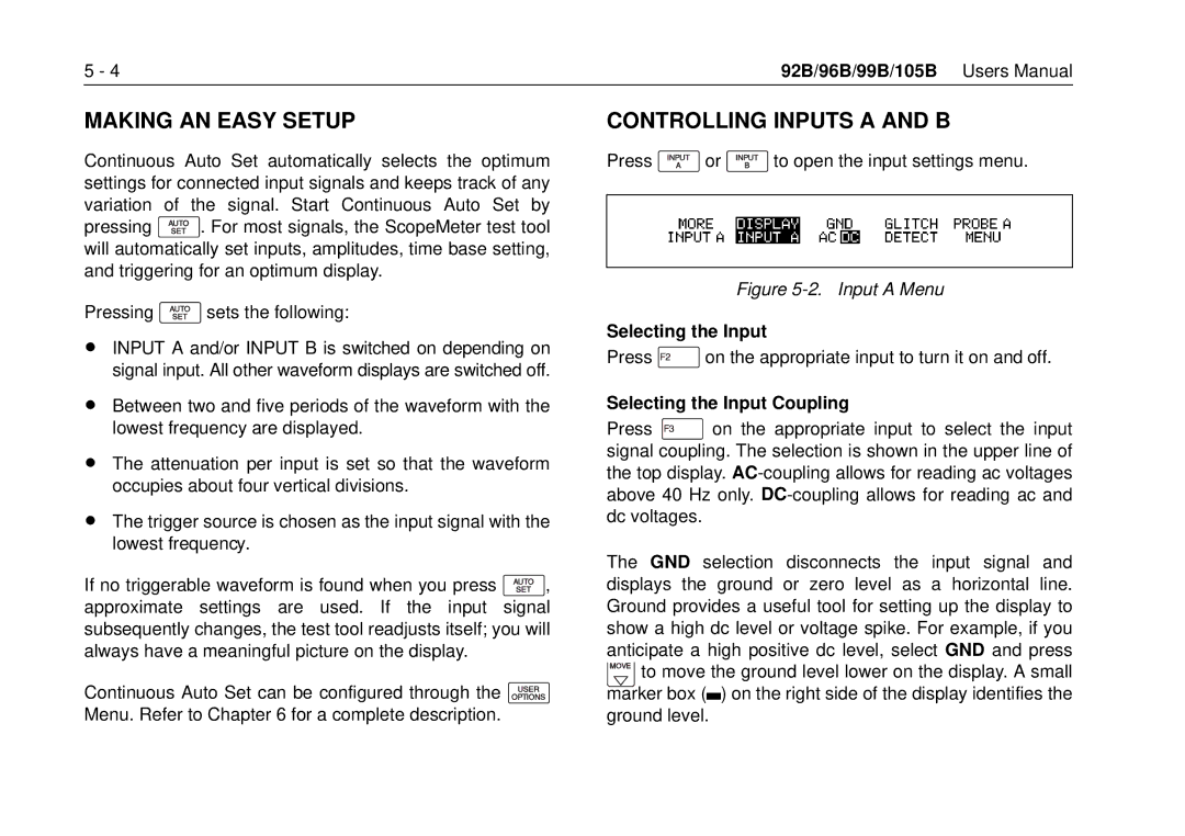
Both oscilloscopes are equipped with advanced display technology, offering clear and bright visual output. The intuitive user interface allows for easy navigation and configuration, enabling users to quickly set up their measurements without a steep learning curve. High-resolution displays provide detailed waveform representation, enhancing the ability to analyze complex signals.
In terms of connectivity, the Fluke 105B and 99B include multiple input channels, often allowing for simultaneous measurement of multiple signals. This is particularly useful in troubleshooting applications where the relationship between signals needs to be understood. The oscilloscopes also support various triggering modes, which provide users the flexibility to isolate specific signal events for more focused analysis.
The portability of the Fluke 105B and 99B cannot be overlooked. With their lightweight design and battery operation capabilities, these oscilloscopes are well-suited for fieldwork, enabling technicians to conduct live measurements without being tethered to a power source. This makes troubleshooting and validation of electrical systems much more convenient, especially in remote locations or on-site environments.
Powerful storage features allow users to capture, save, and export waveform data for further analysis or reporting. The availability of software for data analysis and documentation enhances the functionality of both models, making it easier to maintain a record of measurements and findings.
In summary, the Fluke 105B and 99B oscilloscopes are powerful, portable, and equipped with advanced features that cater to various testing and diagnostic scenarios. Their robust design, high-performance specifications, and user-friendly interfaces make them a valuable addition to any electronics professional's toolkit, ensuring reliable performance in the field.

