124, 123 specifications
The Fluke 123 and 124 are part of Fluke's innovative range of handheld oscilloscopes designed for electrical and industrial maintenance professionals. These devices combine oscilloscopes with digital multimeter capabilities, making them invaluable tools for troubleshooting and maintenance tasks.One of the standout features of the Fluke 123 and 124 is their ability to perform real-time waveforms and measurements. Equipped with a 2.5-inch color display, these oscilloscopes provide clear and detailed visualizations of electrical signals. The Fluke 123 offers a bandwidth of 20 MHz, while the Fluke 124 takes it a step further with a bandwidth of 40 MHz, making them versatile tools for various electrical applications.
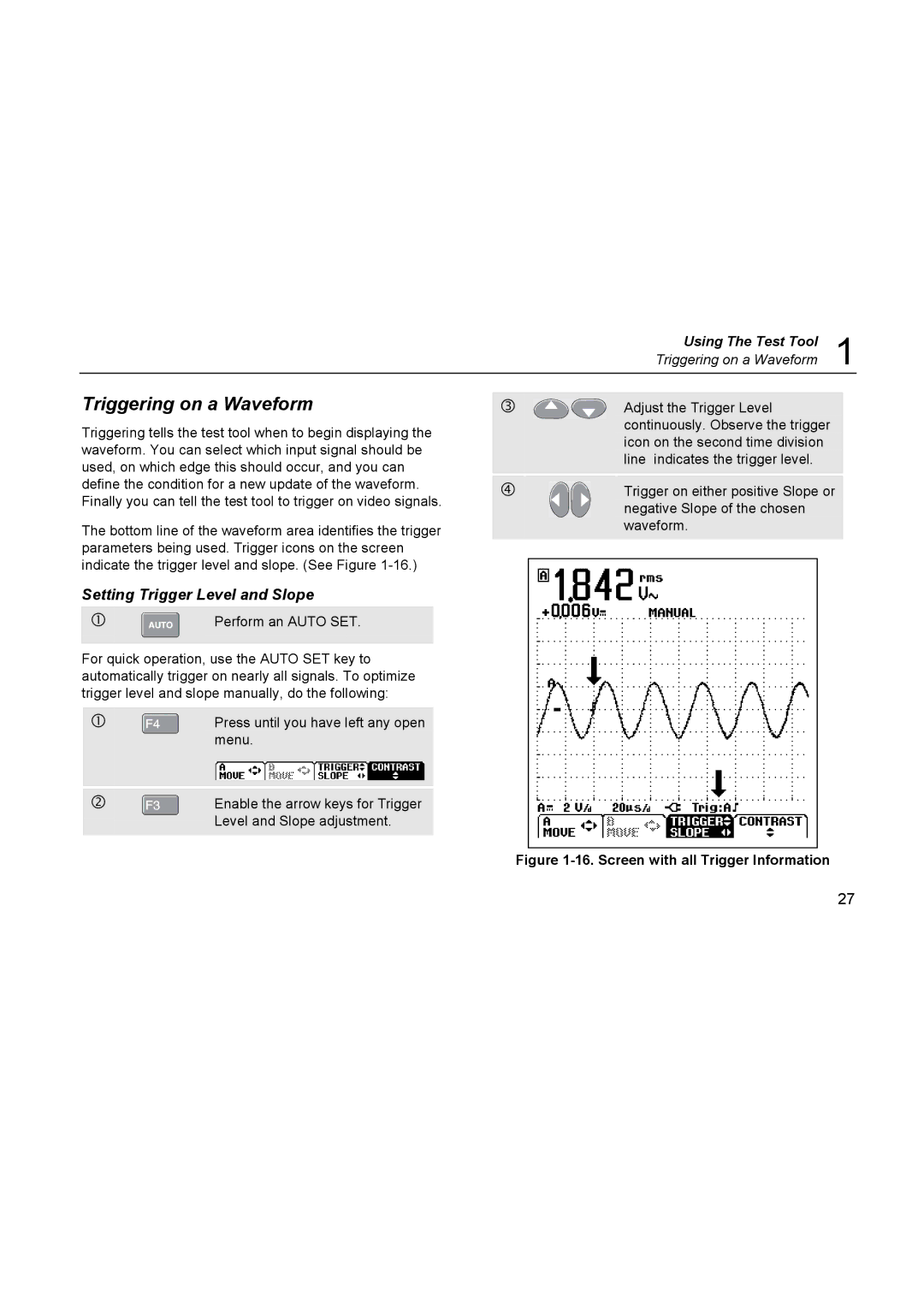
Both models feature a unique "VPE" (Voltage, Period, and Edge) measurement capability, allowing users to capture electrical signals with precision. This feature is particularly useful in identifying signal distortions and voltage fluctuations, which can lead to equipment failures. Additionally, these devices come with various trigger functions, enabling users to analyze intermittent faults and complex signal behaviors effectively.
Another important characteristic of the Fluke 123 and 124 is their robust design. Built to withstand harsh working environments, they boast an IP51 rating for protection against dust and moisture. The ergonomic design ensures comfort during prolonged use, while the easy-to-navigate interface simplifies its operation.
In terms of battery life, both models are equipped with long-lasting rechargeable batteries, ensuring that users can operate them for extended periods without interruption. Furthermore, they offer storage capabilities for waveform captures, which can be later analyzed or shared with colleagues, enhancing collaboration during troubleshooting efforts.
The Fluke 124 also includes advanced features such as a built-in recording function, allowing users to log measurements over time. This is especially useful for monitoring electrical parameters in industrial processes and systems. Moreover, both models support various probes, giving users the flexibility to tackle different measurement scenarios.
In conclusion, the Fluke 123 and 124 are essential tools for professionals in the electrical and industrial sectors. Their combination of oscilloscope and multimeter functionality, robust design, and advanced measurement capabilities make them ideal for effectively diagnosing and troubleshooting a wide range of electrical issues. Whether it’s for routine maintenance or complex troubleshooting, these devices provide the accuracy and reliability necessary for today's demanding environments.

