16. Remove the plug from the mains : | Maintenance and storage |
|
| ||||||
- | before leaving the mower unattended for any period; | 1. | Keep all nuts, bolts and screws tight to be sure the | ||||||
- | before clearing a blockage; |
| lawnmower is in safe working condition. | ||||||
- | before checking, cleaning or working on the appli- | 2. | Check the grassbox frequently for wear or deterioration. | ||||||
| ance; | 3. | Replace worn or damaged parts for safety. | ||||||
- | if you hit an object. Do not use your lawnmower | 4. | Only use the replacement blade, blade bolt, spacer | ||||||
| until you are sure that the entire lawnmower is in a |
| and impeller specified for this product. | ||||||
| safe operating condition.; | 5. | Be careful during adjustment of the lawnmower to | ||||||
- | if the lawnmower starts to vibrate abnormally. Check |
| prevent entrapment of the fingers between moving | ||||||
| immediately. Excessive vibration can cause injury. |
| blades and fixed parts of the machine. | ||||||
|
|
|
|
| |||||
|
|
|
|
| |||||
CABLES | MAINS PLUG REPLACEMENT |
|
| ||||||
IMPORTANT | IMPORTANT |
|
|
|
|
| |||
• | Use only 1.00mm2 size cable up to 40 metres length | • | If the plug supplied is cut off it should be | ||||||
| maximum. |
| destroyed. There is an electric shock hazard if a | ||||||
Maximum rating : |
| cut off plug is inserted into a 13 amp socket. | |||||||
1.00mm2 size cable, 10 amps 250 volts AC. | 1. | No earth required. Flymo products are double insulat- | |||||||
• | YOUR LAWNMOWER IS SUPPLIED WITH AN |
| ed to EN60335 and under no circumstances should an | ||||||
| ELECTRIC MAINS CABLE FITTED WITH A |
| earth be connected to any part of the product. | ||||||
| FEMALE CONNECTOR. | 2. | Ensure the mains voltage suits your product | ||||||
1. | Flymo Mains Cables and Extension Cables are | 3. | IMPORTANT! |
|
|
| |||
| available from your local Electrolux Outdoor |
|
|
|
|
|
|
|
|
| Products Approved Service Centre. |
|
| E |
|
|
|
|
|
2. | Do not wire an extension cable directly to your prod- |
|
|
|
| The wires in the mains lead are | |||
|
| L |
| RED | |||||
| uct yourself. Please contact your local Electrolux |
|
|
| coloured in accordance with the | ||||
|
|
|
|
| OR | ||||
| Outdoor Products Approved Service Centre for fur- |
|
|
| F | BROWN | following code: |
| |
| BLACK |
| U |
|
| ||||
| ther information on the connectors and kits avail- |
| S |
| BLUE | - | NEUTRAL | ||
| OR |
| N | E |
| ||||
| BLUE |
|
| ||||||
| able. |
|
|
|
|
| BROWN | - | LIVE |
3. | Only use extension cables specifically designed for |
|
|
|
|
|
|
|
|
| outdoor use. |
|
|
|
|
|
|
|
|
CONNECTORS |
|
|
|
|
|
|
|
| |
IMPORTANT | The wire which is coloured BLUE must be connected to the | ||||||||
• | Flymo connectors are suitable for use with 2 core | Terminal which is marked with the letter 'N' or coloured BLACK. | |||||||
| cable only. Under no circumstances should these | The wire which is coloured BROWN must be connected to the | |||||||
| connectors be used for earthed products. | Terminal which is marked with the letter 'L' or coloured RED. | |||||||
• | All Flymo connectors and cables are of splashproof | 4. | It is important that the outer sheath is clamped cor- | ||||||
| construction. They are not waterproof and must not |
| rectly into the |
|
| ||||
| be left outside permanently nor should they be sub- | 5. | If in doubt consult your local Service Repairer or | ||||||
| merged or immersed in water. Do not let cable lay |
| qualified electrician before the machine is used. | ||||||
| or trail through pools of water or splashed with | 6. | A 13 Amp fuse must be fitted to the Mains Plug. | ||||||
| water from hose pipes. | 7. | The normal plug fuse and household fuse only pro- | ||||||
|
|
| tect the electrical equipment and are not a safe- | ||||||
|
|
| guard against electrocution. |
|
| ||||
|
|
|
|
|
|
|
|
|
|
Assembly Instructions
A1 |
|
B1 | ensure |
| the point |
| of the |
| screw |
| stays |
| inside |
| the han- |
| dle |
C1 |
|
A2 |
B2 |
C2 |
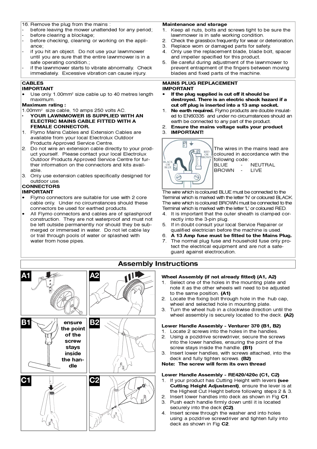
Wheel Assembly (if not already fitted) (A1, A2)
1.Select one of the holes in the mounting plate and
note it as the other wheels will need to be adjusted to the same position. (A1)
2.Locate the fixing bolt through hole in the hub cap, wheel and selected hole in mounting plate.
3.Turn the wheel hub in a clockwise direction until the wheel assembly is securely located to the deck. (A2)
Lower Handle Assembly - Venturer 370 (B1, B2)
1.Locate 2 screws into the holes in the handles.
2.Using a pozidrive screwdriver, secure the screws
into the lower handles, ensuring the point of the screw stays inside the handle. (B1)
3.Insert lower handles, with screws attached, into the
deck and fully tighten screws. (B2)
Note: The screw will form its own thread
Lower Handle Assembly - RE420/420c (C1, C2)
1.If your product has Cutting Height with levers (see Cutting Height Adjustment), ensure the lever is at the Highest Cut Height before following steps 2 & 3.
2.Insert lower handles into deck as shown in Fig C1.
3.Push each handle firmly down until it is located securely into the deck (C2).
4.Insert screw through the washer and into holes
using a pozidrive screwdriver and tighten fully into deck as shown in Fig C2.