OWNER’S MANUAL
INSTALLATION
Continued
![]() CAUTION: Use pipe joint seal- ant that is resistant to liquid pe- troleum (LP) gas.
CAUTION: Use pipe joint seal- ant that is resistant to liquid pe- troleum (LP) gas.
We recommend that you install a sediment trap in supply line as shown in Figure 24, page 14. Locate sediment trap where it is within reach for cleaning. Install in piping
![]() CAUTION: Avoid damage to regulator. Hold gas regulator with wrench when connecting it to gas piping and/or fittings.
CAUTION: Avoid damage to regulator. Hold gas regulator with wrench when connecting it to gas piping and/or fittings.
4.Apply pipe joint sealant lightly to male threads of gas connector attached to flexible gas line/equipment shutoff valve (see Figure 26).
5.Check all gas connections for leaks. See Checking Gas Connections, page 16.
6.Replace branch support back into fire- place. Feed flexible gas line into fire- place base area while replacing branch support. Make sure the entire flexible gas line is in fireplace base area. Reat- tach branch support to fireplace with screws removed in step 2.
system between fuel supply and heater. Locate sediment trap where trapped matter is not likely to freeze. A sediment trap traps moisture and contaminants. This keeps them from going into fireplace controls. If sedi- ment trap is not installed or is installed wrong, fireplace may not run properly.
CONNECTING EQUIPMENT SHUTOFF VALVE TO HEATER CONTROL
Installation Items Needed
•Phillips screwdriver
•sealant (resistant to propane/LP gas, not provided)
1. Remove fireplace screen. Remove two |
screws that hold fireplace screen in |
place for shipping. These screws are |
located near top of screen. Discard |
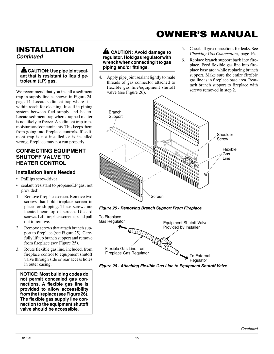
Branch
Support
Shoulder
Screw
Flexible
Gas
Line
Screen
Figure 25 - Removing Branch Support From Fireplace
| screws. Lift fireplace screen up and pull |
| out to remove. |
2. | Remove screws that attach branch sup- |
| port to fireplace (see Figure 25). Care- |
| fully lift up branch support and remove |
| from fireplace (see Figure 25). |
3. | Route flexible gas line, included, from |
| fireplace control to equipment shutoff |
| valve through side or rear access holes |
| in outer casing. |
To Fireplace
Gas Regulator
➞![]()
Flexible Gas Line from Fireplace Gas Regulator
Equipment Shutoff Valve Provided by Installer
➞ | To External |
| |
| Regulator |
NOTICE: Most building codes do not permit concealed gas con- nections. A flexible gas line is provided to allow accessibility from the fireplace (see Figure 26). The flexible gas supply line con- nection to the equipment shutoff valve should be accessible.
Figure 26 - Attaching Flexible Gas Line to Equipment Shutoff Valve
Continued
107106 | 15 |