OPERATING INSTRUCTIONS

CONTROL BOARD FUNCTIONS

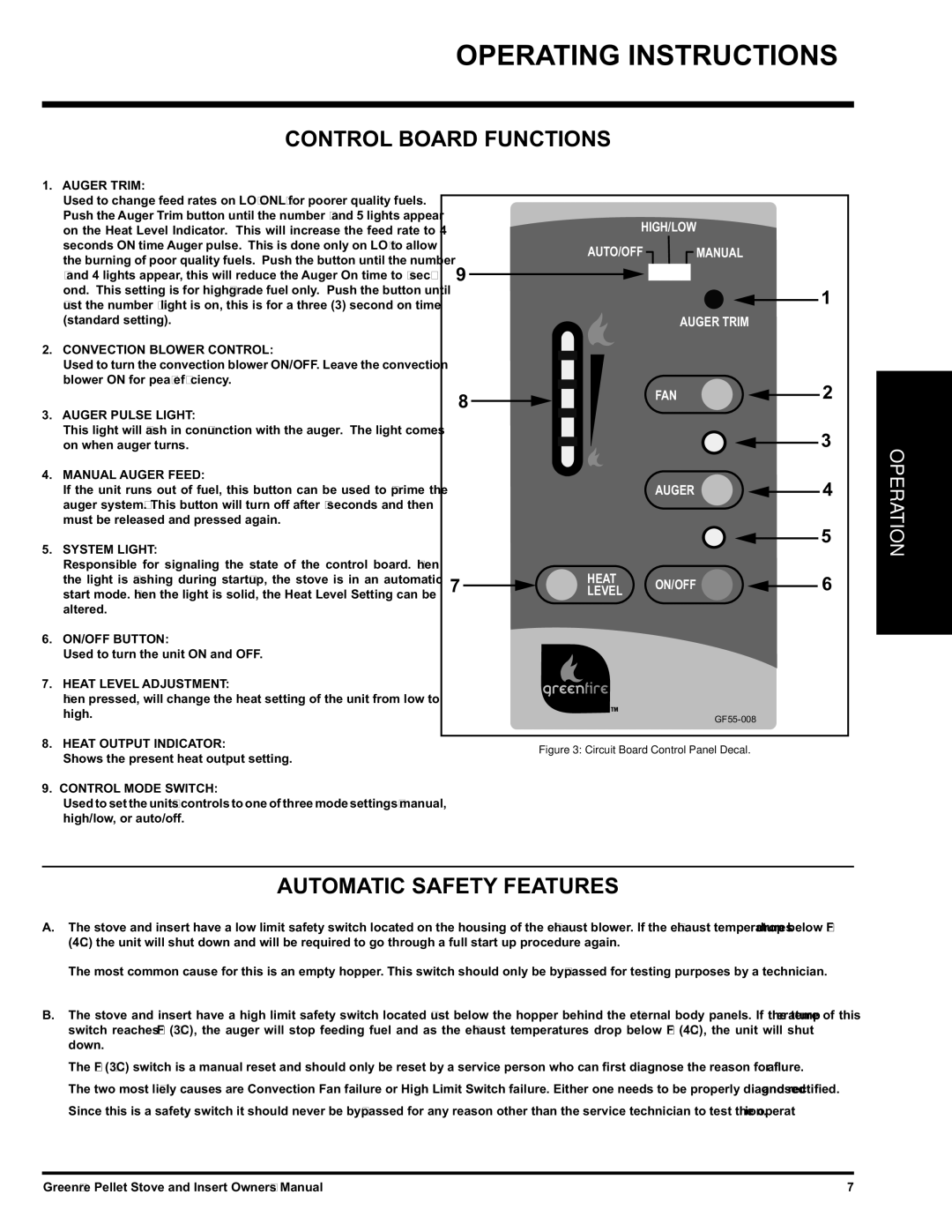
1.AUGER TRIM:

Used to change feed rates on LOW ONLY for poorer quality fuels. Push the Auger Trim button until the number 1 and 5 lights appear on the Heat Level Indicator. This will increase the feed rate to 4 seconds ON time Auger pulse. This is done only on LOW to allow the burning of poor quality fuels. Push the button until the number 1 and 4 lights appear, this will reduce the Auger On time to 2 sec- ond. This setting is for high-grade fuel only. Push the button until just the number 1 light is on, this is for a three (3) second on time (standard setting).

2.CONVECTION BLOWER CONTROL:

Used to turn the convection blower ON/OFF. Leave the convection blower ON for peak efficiency.

3.AUGER PULSE LIGHT:

This light will fl ash in conjunction with the auger. The light comes on when auger turns.

4.MANUAL AUGER FEED:

If the unit runs out of fuel, this button can be used to “prime the auger system”. This button will turn off after 60 seconds and then must be released and pressed again.

5.SYSTEM LIGHT:

Responsible for signaling the state of the control board. When the light is fl ashing during start-up, the stove is in an automatic start mode. When the light is solid, the Heat Level Setting can be altered.

6.ON/OFF BUTTON:

Used to turn the unit ON and OFF.

7.HEAT LEVEL ADJUSTMENT:

When pressed, will change the heat setting of the unit from low to high.

8.HEAT OUTPUT INDICATOR:

Shows the present heat output setting.

9.CONTROL MODE SWITCH:

Used to set the unit’s controls to one of three mode settings; manual,

high/low, or auto/off.


HIGH/LOW


AUTO/OFF

MANUAL


9


1


AUGER TRIM


8


FAN

2


3

OPERATION


AUGER

4


5


7

HEAT

ON/OFF

6


LEVEL


GF55-008


Figure 3: Circuit Board Control Panel Decal.

AUTOMATIC SAFETY FEATURES

A.The stove and insert have a low limit safety switch located on the housing of the exhaust blower. If the exhaust temperatures drop below 120°F (49°C) the unit will shut down and will be required to go through a full start up procedure again.

The most common cause for this is an empty hopper. This switch should only be by-passed for testing purposes by a technician.

B.The stove and insert have a high limit safety switch located just below the hopper behind the external body panels. If the temperature of this switch reaches 200°F (93°C), the auger will stop feeding fuel and as the exhaust temperatures drop below 120°F (49°C), the unit will shut down.

The 200°F (93°C) switch is a manual reset and should only be reset by a service person who can first diagnose the reason for failure.

The two most likely causes are Convection Fan failure or High Limit Switch failure. Either one needs to be properly diagnosed and rectified. Since this is a safety switch it should never be by-passed for any reason other than the service technician to test the operation.

Greenfi re Pellet Stove and Insert Owner's Manual

7

Page 7
Image 7
FMI GFI55, GF55 owner manual Operating Instructions, Control Board Functions, Automatic Safety Features

GF55, GFI55 specifications

The FMI GF55 and GFI55 are two notable models in the world of high-performance power generation and distribution, catering to various industrial and commercial applications. Both models are designed with cutting-edge technology and engineering, making them reliable solutions for today's energy demands.

The FMI GF55 is a gas-powered generator offering high efficiency and low emissions. Designed for various uses, from construction sites to emergency backup power, this generator boasts a robust 55 kVA output. Its compact design allows for easy transportation and installation, making it a preferred choice for contractors and businesses needing portable power. The generator is equipped with a silent operation feature, ensuring minimal noise pollution, which is particularly advantageous in residential areas or sensitive environments.

On the other hand, the GFI55 model stands out for its advanced inverter technology. This technology enables stable power supply with minimal harmonic distortion, making it suitable for sensitive electronic equipment. The GFI55 is also built with durability in mind, using high-quality materials that ensure a longer lifespan and reduced maintenance needs. Its lightweight structure, combined with an easy-to-use interface, allows operators to quickly set up and utilize the generator.

In terms of connectivity, both models feature multiple output options, allowing users to connect various devices simultaneously. This versatility is a significant advantage for users who require power for multiple applications at once. Additionally, FMI prioritizes safety, equipping both the GF55 and GFI55 with various safety features such as overload protection and automatic shutdown to prevent damage during operational anomalies.

Both models incorporate fuel-efficient technologies that minimize running costs while maximizing performance. They are designed to comply with stringent environmental regulations, ensuring reduced carbon footprints for operations. This feature is growing in importance as industries increasingly pivot towards sustainable practices.

In conclusion, the FMI GF55 and GFI55 represent the best in power generation technology, combining efficiency, functionality, and safety in a compact design. Businesses and contractors looking for reliable, durable, and environmentally friendly power solutions will find these models effective and economical for their operational needs.