2.For The Installer
2.1Important Operating Requirements
| MINIMUM | MAXIMUM |
Air Temperature | 10° C (50° F) | 38° C (100° F) |
Water Temperature | 5° C (40° F) | 38° C (100° F) |
Water Pressures | 1 bar gauge | 5 bar gauge |
Electrical Voltage | | |
Variations Voltage | | |
Rating Specified on Nameplate | –10% | +10% |
Extended periods of operation exceeding these limitations constitute misuse under the terms of manufacturer’s Limited Warranty, resulting in a loss of warranty coverage.
INSTALLATION NOTE: Allow 15cm minimum space at sides and back for ventilation and utility connections.
2.2Select Location
The first step in installing the equipment is to select the location. The purchaser of the unit will have a desired spot in mind, ensure that it is:
•indoors, in an environment that does not exceed the air and water temperature limitations for the equipment.
•that the necessary utilities are available including the correct voltage electrical power.
•that there is space around the installed machine for service, 15cm minimum left, right, and rear for air-cooled models.
2.3Ice Machine
The use of a mechanical lift is recommended for lifting the uncrated ice maker onto the bin.
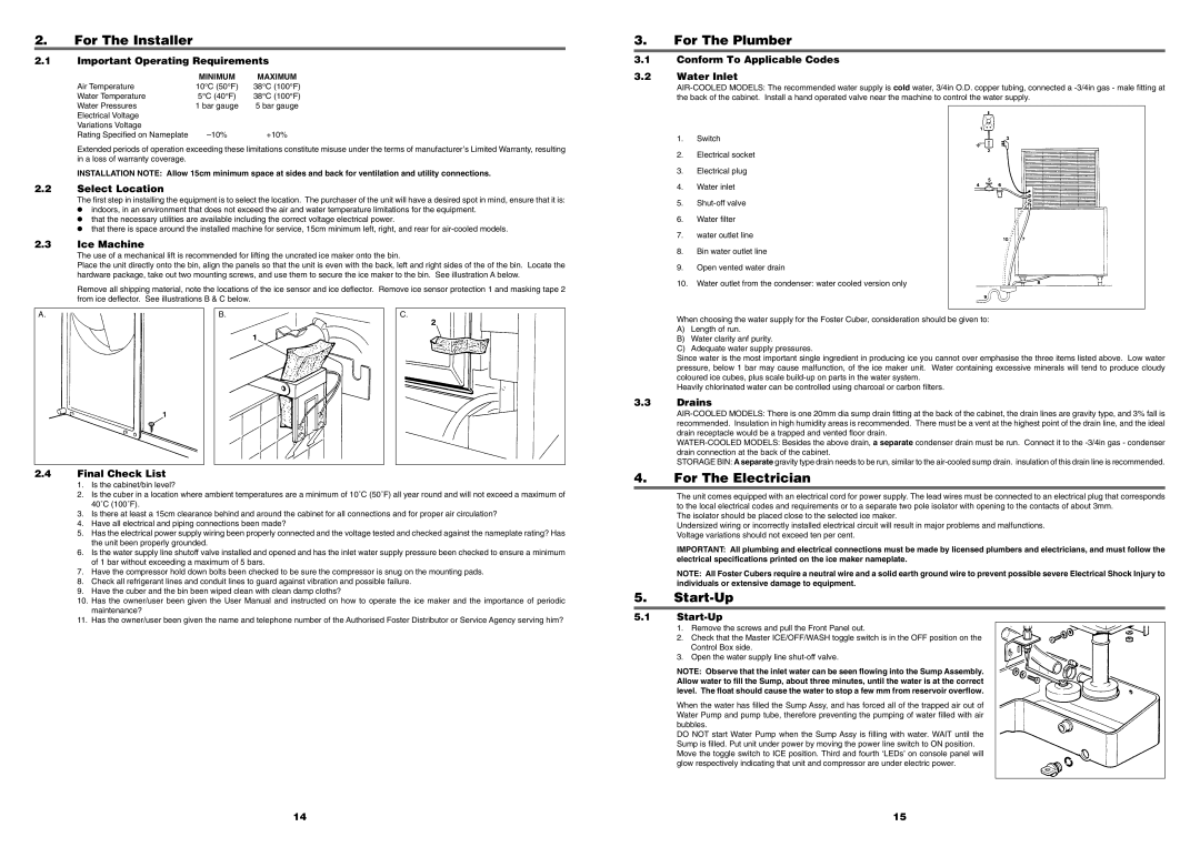
Place the unit directly onto the bin, align the panels so that the unit is even with the back, left and right sides of the of the bin. Locate the hardware package, take out two mounting screws, and use them to secure the ice maker to the bin. See illustration A below.
Remove all shipping material, note the locations of the ice sensor and ice deflector. Remove ice sensor protection 1 and masking tape 2 from ice deflector. See illustrations B & C below.
2.4Final Check List
1.Is the cabinet/bin level?
2.Is the cuber in a location where ambient temperatures are a minimum of 10˚C (50˚F) all year round and will not exceed a maximum of 40˚C (100˚F).
3.Is there at least a 15cm clearance behind and around the cabinet for all connections and for proper air circulation?
4.Have all electrical and piping connections been made?
5.Has the electrical power supply wiring been properly connected and the voltage tested and checked against the nameplate rating? Has the unit been properly grounded.
6.Is the water supply line shutoff valve installed and opened and has the inlet water supply pressure been checked to ensure a minimum of 1 bar without exceeding a maximum of 5 bars.
7.Have the compressor hold down bolts been checked to be sure the compressor is snug on the mounting pads.
8.Check all refrigerant lines and conduit lines to guard against vibration and possible failure.
9.Have the cuber and the bin been wiped clean with clean damp cloths?
10.Has the owner/user been given the User Manual and instructed on how to operate the ice maker and the importance of periodic maintenance?
11.Has the owner/user been given the name and telephone number of the Authorised Foster Distributor or Service Agency serving him?
3.For The Plumber
3.1Conform To Applicable Codes
3.2Water Inlet
AIR-COOLED MODELS: The recommended water supply is cold water, 3/4in O.D. copper tubing, connected a -3/4in gas - male fitting at the back of the cabinet. Install a hand operated valve near the machine to control the water supply.
1.Switch
2.Electrical socket
3.Electrical plug
4.Water inlet
5.Shut-off valve
6.Water filter
7.water outlet line
8.Bin water outlet line
9.Open vented water drain
10.Water outlet from the condenser: water cooled version only
When choosing the water supply for the Foster Cuber, consideration should be given to:
A)Length of run.
B)Water clarity anf purity.
C)Adequate water supply pressures.
Since water is the most important single ingredient in producing ice you cannot over emphasise the three items listed above. Low water pressure, below 1 bar may cause malfunction, of the ice maker unit. Water containing excessive minerals will tend to produce cloudy coloured ice cubes, plus scale build-up on parts in the water system.
Heavily chlorinated water can be controlled using charcoal or carbon filters.
3.3Drains
AIR-COOLED MODELS: There is one 20mm dia sump drain fitting at the back of the cabinet, the drain lines are gravity type, and 3% fall is recommended. Insulation in high humidity areas is recommended. There must be a vent at the highest point of the drain line, and the ideal drain receptacle would be a trapped and vented floor drain.
WATER-COOLED MODELS: Besides the above drain, a separate condenser drain must be run. Connect it to the -3/4in gas - condenser drain connection at the back of the cabinet.
STORAGE BIN: A separate gravity type drain needs to be run, similar to the air-cooled sump drain. insulation of this drain line is recommended.
4.For The Electrician
The unit comes equipped with an electrical cord for power supply. The lead wires must be connected to an electrical plug that corresponds to the local electrical codes and requirements or to a separate two pole isolator with opening to the contacts of about 3mm.
The isolator should be placed close to the selected ice maker.
Undersized wiring or incorrectly installed electrical circuit will result in major problems and malfunctions.
Voltage variations should not exceed ten per cent.
IMPORTANT: All plumbing and electrical connections must be made by licensed plumbers and electricians, and must follow the electrical specifications printed on the ice maker nameplate.
NOTE: All Foster Cubers require a neutral wire and a solid earth ground wire to prevent possible severe Electrical Shock Injury to individuals or extensive damage to equipment.
5.Start-Up
5.1Start-Up
1.Remove the screws and pull the Front Panel out.
2.Check that the Master ICE/OFF/WASH toggle switch is in the OFF position on the Control Box side.
3.Open the water supply line shut-off valve.
NOTE: Observe that the inlet water can be seen flowing into the Sump Assembly. Allow water to fill the Sump, about three minutes, until the water is at the correct level. The float should cause the water to stop a few mm from reservoir overflow.
When the water has filled the Sump Assy, and has forced all of the trapped air out of Water Pump and pump tube, therefore preventing the pumping of water filled with air bubbles.
DO NOT start Water Pump when the Sump Assy is filling with water. WAIT until the Sump is filled. Put unit under power by moving the power line switch to ON position. Move the toggle switch to ICE position. Third and fourth ‘LEDs’ on console panel will glow respectively indicating that unit and compressor are under electric power.