2.Start Up.
2.1Start–up Cycle.
Open the water valve and switch on the power to the machine.
The machine enters the Start-Up mode with the energising of the PC Board with the green LED (Power On) illuminated. It is necessary to remove the front cover of the machine to see all of the LED’s.
The Green LED of Machine In Operation is also energised, blinking fast for 40 seconds prior to the start up of the machine.
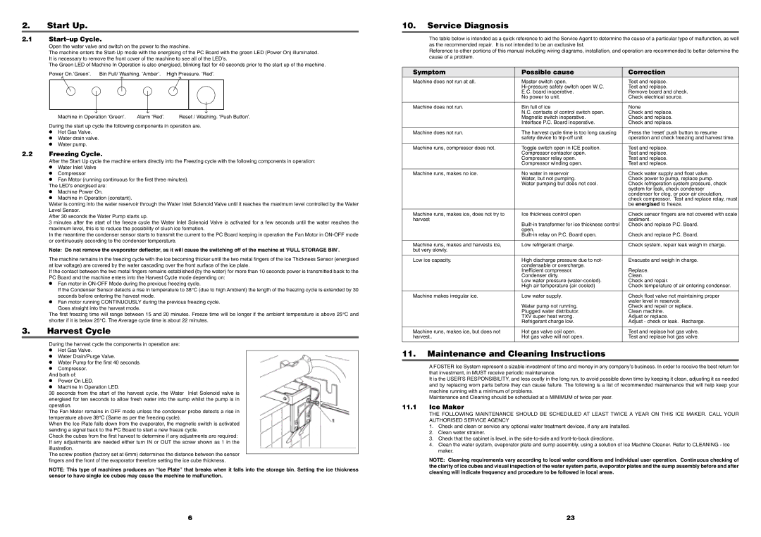
Power On.‘Green’. | Bin Full/ Washing. ‘Amber’. High Pressure. ‘Red’. |
| | |
| | |
Machine in Operation ‘Green’. | Alarm ‘Red’. | Reset / Washing. ‘Push Button’. |
During the start up cycle the following components in operation are.
•Hot Gas Valve.
•Water drain valve.
•Water pump.
2.2Freezing Cycle.
After the Start Up cycle the machine enters directly into the Freezing cycle with the following components in operation:
•Water Inlet Valve
•Compressor
•Fan Motor (running continuous for the first three minutes). The LED’s energised are:
•Machine Power On.
•Machine in Operation (constant).
Water is coming into the water reservoir through the Water Inlet Solenoid Valve until it reaches the maximum level controlled by the Water Level Sensor.
After 30 seconds the Water Pump starts up.
3 minutes after the start of the freeze cycle the Water Inlet Solenoid Valve is activated for a few seconds until the water reaches the maximum level, this is to reduce the possibility of slush ice formation.
In the meantime the condenser sensor starts to transmit the current to the PC Board keeping in operation the Fan Motor in ON-OFF mode or continuously according to the condenser temperature.
Note: Do not remove the evaporator deflector, as it will cause the switching off of the machine at ‘FULL STORAGE BIN’.
The machine remains in the freezing cycle with the ice becoming thicker until the two metal fingers of the Ice Thickness Sensor (energised at low voltage) are covered by the water cascading over the front surface of the ice plate.
If the contact between the two metal fingers remains established (by the water) for more than 10 seconds power is transmitted back to the PC Board and the machine enters into the Harvest Cycle mode depending on:
•Fan motor in ON-OFF Mode during the previous freezing cycle.
If the Condenser Sensor detects a rise in temperature to 38° C (due to high Ambient) the length of the freezing cycle is extended by 30 seconds before entering the harvest mode.
•Fan motor running CONTINUOUSLY during the previous freezing cycle.
Goes straight into the harvest mode.
The first freezing time will range between 15 and 20 minutes. Freeze time will be longer if the ambient temperature is above 25° C and shorter if it is below 25° C. The Average cycle time is about 22 minutes.
3.Harvest Cycle
During the harvest cycle the components in operation are:
•Hot Gas Valve.
•Water Drain/Purge Valve.
•Water Pump for the first 40 seconds.
•Compressor.
And both of:
•Power On LED.
•Machine In Operation LED.
30 seconds from the start of the harvest cycle, the Water Inlet Solenoid valve is energised for ten seconds to allow fresh water into the sump whilst the pump is in operation.
The Fan Motor remains in OFF mode unless the condenser probe detects a rise in temperature above 38° C (Same as per the freezing cycle).
When the Ice Plate falls down from the evaporator, the magnetic switch is activated sending a signal back to the PC Board to start a new freeze cycle.
Check the cubes from the first harvest to determine if any adjustments are required: If any adjustments are needed either turn IN or OUT the screw shown as 1 in the illustration.
The screw position (factory set at 6mm) determines the distance between the sensor fingers and the front of the evaporator therefore setting the ice cube thickness.
NOTE: This type of machines produces an “Ice Plate” that breaks when it falls into the storage bin. Setting the ice thickness sensor to have single ice cubes may cause the machine to malfunction.
10.Service Diagnosis
The table below is intended as a quick reference to aid the Service Agent to determine the cause of a particular type of malfunction, as well as the recommended repair. It is not intended to be an exclusive list.
Reference to other portions of this manual including wiring diagrams, installation, and operation are recommended to better determine the cause of a problem.
Symptom | Possible cause | Correction |
Machine does not run at all. | Master switch open. | Test and replace. |
| Hi-pressure safety switch open W.C. | Test and replace. |
| E.C. board inoperative. | Remove board and check. |
| No power to unit. | Check electrical source. |
| | |
Machine does not run. | Bin full of ice | None |
| N.C. contacts of control switch open. | Check and replace. |
| Magnetic switch inoperative. | Check and replace. |
| Interface P.C. Board inoperative. | Check and replace. |
| | |
Machine does not run. | The harvest cycle time is too long causing | Press the ‘reset’ push button to resume |
| safety device to trip-off unit | operation and check freezing and harvest time. |
| | |
Machine runs, compressor does not. | Toggle switch open in ICE position. | Test and replace. |
| Compressor contactor open. | Test and replace. |
| Compressor relay open. | Test and replace. |
| Compressor winding open. | Test and replace. |
| | |
Machine runs, makes no ice. | No water in reservoir | Check water supply and float valve. |
| Water, but not pumping. | Check power to pump, replace pump. |
| Water pumping but does not cool. | Check refrigeration system pressure, check |
| | system for leak, check condenser |
| | condenser for clog, or poor air circulation, |
| | check compressor. Test and replace relay, must |
| | be energised to freeze. |
| | |
Machine runs, makes ice, does not try to | Ice thickness control open | Check sensor fingers are not covered with scale |
harvest | | sediment. |
| Built-in transformer for ice thickness control | Check and replace P.C. Board. |
| open. | |
| Built-in relay on P.C. Board open. | Check and replace P.C. Board. |
| | |
Machine runs, makes and harvests ice, | Low refrigerant charge. | Check system, repair leak weigh in charge. |
but very slowly. | | |
| | |
Low ice capacity. | High discharge pressure due to not- | Evacuate and weigh in charge. |
| condensable or overcharge. | |
| Inefficient compressor. | Replace. |
| Condenser dirty. | Clean. |
| Low water pressure (water-cooled). | Check and repair. |
| High air temperature (air cooled) | Check temperature of air entering condenser. |
| | |
Machine makes irregular ice. | Low water supply. | Check float valve not maintaining proper |
| | water level in reservoir. |
| Water pump not running. | Check and repair or replace. |
| Plugged water distributor. | Clean machine. |
| TXV super heat wrong. | Adjust or replace. |
| Refrigerant charge low. | Adjust - check or leak. Recharge. |
| | |
Machine runs, makes ice, but does not | Hot gas valve coil open. | Test and replace hot gas valve. |
harvest.. | Hot gas valve will not open. | Test and replace hot gas valve. |
| | |
11.Maintenance and Cleaning Instructions
A FOSTER Ice System represent a sizable investment of time and money in any company’s business. In order to receive the best return for that investment, in MUST receive periodic maintenance.
It is the USER’S RESPONSIBILITY, and less costly in the long run, to avoid possible down time by keeping it clean, adjusting it as needed and by replacing worn parts before they can cause failure. The following is a list of recommended maintenance that will help keep your machine running with a minimum of problems.
Maintenance and Cleaning should be scheduled at a MINIMUM of twice per year.
11.1Ice Maker
THE FOLLOWING MAINTENANCE SHOULD BE SCHEDULED AT LEAST TWICE A YEAR ON THIS ICE MAKER. CALL YOUR AUTHORISED SERVICE AGENCY
1.Check and clean or service any optional water treatment devices, if any are installed.
2.Clean water strainer.
3.Check that the cabinet is level, in the side-to-side and front-to-back directions.
4.Clean the water system, evaporator plate and sump assembly, using a solution of Ice Machine Cleaner. Refer to CLEANING - Ice maker.
NOTE: Cleaning requirements vary according to local water conditions and individual user operation. Continuous checking of the clarity of ice cubes and visual inspection of the water system parts, evaporator plates and the sump assembly before and after cleaning will indicate frequency and procedure to be followed in local areas.