DVD Master Recorder
Model
Safety Instructions
Table of Contents
Storing time data
Time code recording
Preview Function
Locate Function
Audio file management
Editing track data
Setup mode
Using a PS/2 keyboard
FTP server function
Importing an audio file to a computer
Specifications
Utility mode
Manual construction
About this manual
Preview Function
Precautions on installation
Precautions
Precautions on safety
DV40 main features
Page
Before using the DV40
Press down the Power switch
Turning on the power
Press the Setup key
Setting the internal clock
Press the ENTER/YES key
Press the ENTER/YES key after enter the value
About usable DVD-RAM disks
Loading a DVD-RAM disk
Press the OPEN/CLOSE key
Formatting a DVD-RAM disk
Normal Mode Tape Mode
Press the ENTER/YES key again
Select the format mode and press the ENTER/YES key
After entering a volume name, press the ENTER/YES key
Tips How to enter a desired label name
About audio files on a formatted disk
Disk formatted in the Normal format mode
No Audio Files
About the time display
Disk formatted in the Tape format mode
If a disk is formatted in the Tape mode
If a disk is formatted in the Normal mode
Press the TR Mode and Sampling Freq switches as desired
About Remain display
Page
Names and Functions
Rear panel
Front panel
Front panel part
Front panel part
Transport keys
List Play Edit key
Keyboard connector
Mouse connector
Monitor section
SKIP/CURSOR , -, + keys
Margin RESET/CLR key
FL display
Disp Time key
Setup Utility key
Disp Level key
File SEL Directory key
Shuttle key
JOG key
ENTER/YES key
EXIT/NO key
DEST-OUT PREVIEW/TR 4 key
CUE Point Preview key
Locate key
DEST-IN PREVIEW/TR 3 key
SOURCE-IN PREVIEW/TR 1 key
Audio Edit key
TC RDY key
Slate Tone Tone REC key
Input MON key
FL display
Alphanumeric keys
Audio File switch
Control switch
Input switch
Pull UP/DOWN switch
Clock switch
TC GEN Mode switch
Analog Input Signal controls
Bypass ON/OFF switch
Analog input/output section
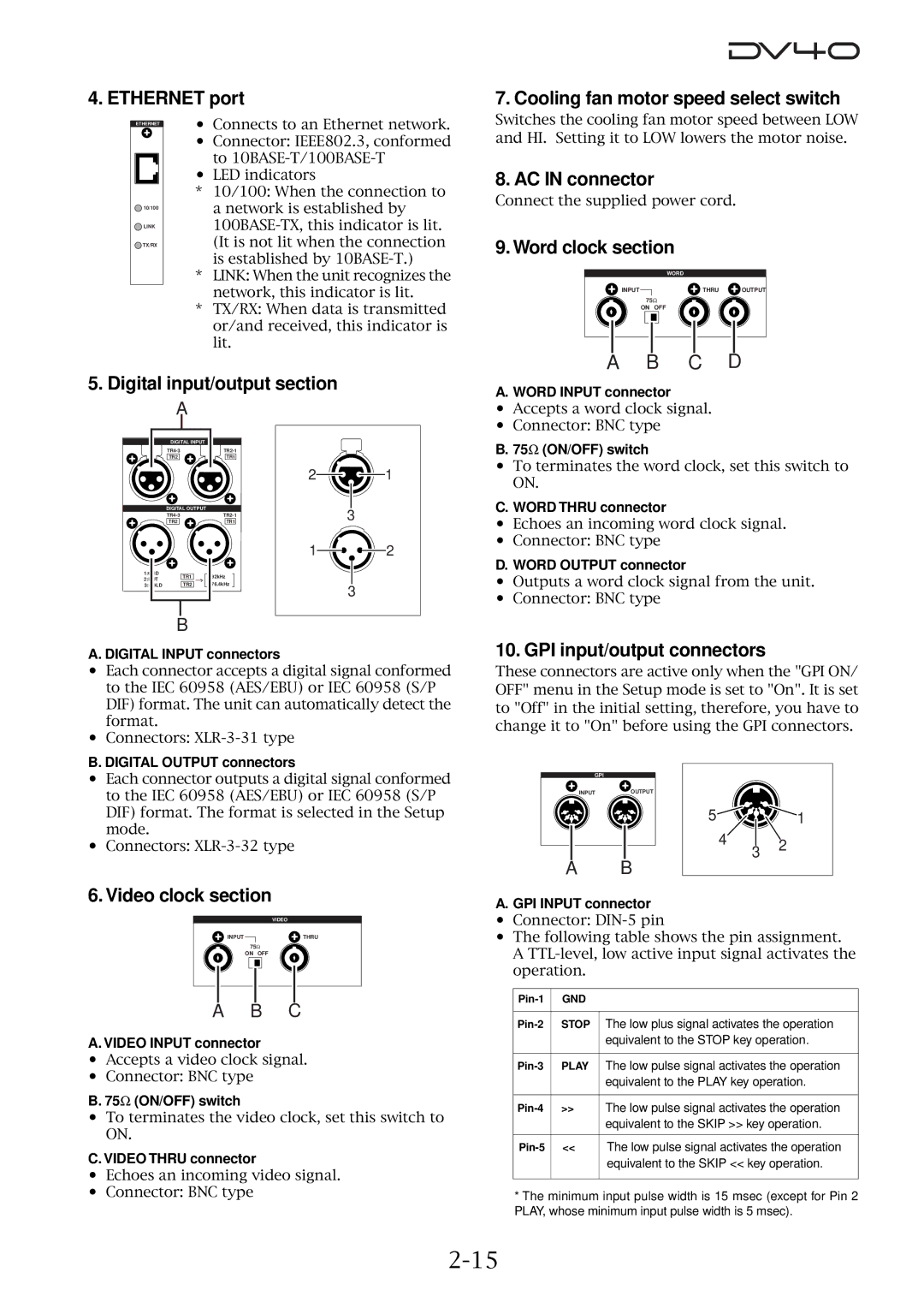
Rear panel
Time code input/output section
Expansion slot
GPI input/output connectors
AC in connector
Ethernet port
Word clock section
Pin remote connector
GPI Output connector
Chapter Reformatting/optimizing a disk
Press the ENTER/YES key again
Reformatting a DVD-RAM disk
Select the format mode and press the ENTER/YES key
Tips How to edit a label name
When selecting Norm
When selecting Tape
Press the ENTER/YES key
Press the EXIT/NO or Stop key
Optimizing a disk
Page
Chapter Audio recording/playback
NEW File mode
About the NEW File and Insert mode
Insert mode
About the expression for audio files in this manual
Connection to external devices
Recording an analog source in the NEW File mode
External Analog Audio Equipment
Preparation for recording
Tips Bypass switch
Recording
Tips Recording level adjustment of analog audio signals
Press the Record key
Tips File number for a newly created file
You can create an audio file before recording
Playback of recorded audio
While holding down the Stop key, press the Rewind key
Press the File SEL key
Press the F FWD key while holding down the Stop key
Recording an analog source in the Insert mode
Press the Undo key
Multiple-undo function
Selecting a desired file on a disk
Set the Audio File switch to the desired position
To select a file of the same file type
To select a file of the different file type
Sdii audio file file No
Recording to a Tape mode audio file in the Insert mode
BWF audio file file No
When the Audio File switch is changed set to Sdii
When the Audio File switch is not changed set to BWF
Tips
Connection to external devices
Recording a digital source in the NEW File mode
External Digital Device
Preparation for recording
Set the Input switch to Digital
Recording
Recording a digital source in the Insert mode
Mute recording
See Setup mode for details about the Mute time setting menu
Creating a mute space during recording
Feeding the slate tone
Slate tone function
Cueing/high speed shuttle by the shuttle function
Cueing by the jog function
Shuttle cueing
High-speed search
Page
Chapter Time code recording
Recording time code together with audio simultaneously
Time code recording
Press the TC RDY key to arm the time code track
Front panel switch settings
Recording external time code
Connection to external devices/Settings of the DV40
To enter the TC Setup mode
TC Setup mode details
Force-jamming to external time code
Setting the internal TC generator start time
Use the jog dial or numeric keys to enter a numeric value
After entering the time, press the ENTER/YES key
Editing the chase offset
Selecting output time code
Use the jog dial or numeric keys to enter a offset value
After entering the offset value, press the ENTER/YES key
Editing the LTC start time
Trimming the chase offset
Catch offset
Chase mode selection
At the desired point, press the ENTER/YES key
Use the jog dial or SKIP/CURSOR / keys to select Chase MD?
TC user bit output selection
Time code output on/off selection while paused
Use the jog dial or SKIP/CURSOR / keys to select Pause TC?
Selecting MDYf as TC Ubit information
Selecting SRNo as TC Ubit information
Selecting DMYf as TC Ubit information
Example-1 Example-2
Page
Chapter Storing time data
Source in key
Location memory keys
Dest in key
Dest OUT key
Capturing a time on the fly
Storing a time to an edit point memory
Storing a time to an edit point using the numeric keys
Memory 01 Last Play Memory
Storing a time to a locate point memory CUE/MEMORY
Tips Bank selection
After completing time entry, press the ENTER/YES key
Storing a time to a locate point using the numeric keys
After completing the name entry, press the ENTER/YES key
Editing a name of CUE or Memory point
Clearing a CUE or Memory point memory
Page
Chapter Locate functions
Location to the beginning ABS0 of an audio file
Variety of locate functions
Location to the end REC END of the current audio file
Location to the last playback start position
When the recorder is stopped, press the Memory key
Location to the last recording start position
Location to the last recording end position
When the recorder is stopped, press only the Locate key
Location to the point where the recorder located last time
When the recorder is stopped, press the CUE Point key
Location to an audio edit point
If the skip mode is set to MEM
Set the Skip Mode? menu in the Setup mode to CUE or MEM
If the skip mode is set to CUE
Location to a Memory point
Page
Chapter Preview function
Preview at an edit point
Preview function
To stop preview, press the Stop or EXIT/NO key
Press the CUE Point or Memory key
Preview at a locate point
After trimming, press the ENTER/YES key
Trimming while previewing audio
Chapter Audio file management
Creating a new audio file
Bwff Sd2f
Selecting a file using the skip function
Selecting a file using the file select function
Selecting an audio file
While stopped, press the SKIP/CURSOR or key
Tips File extension
Editing an audio file name
Enter a desired name
Tips Restoring a deleted file
Deleting an audio file
Restoring a deleted audio file
Press the EXIT/NO or Stop key to exit the Utility mode
Tips File number of the duplication file
Duplicating an audio file
Chapter Editing track data
10-2
Pasting track data
Store the Source IN, Source OUT and Dest in points
Tips SOURCE-PLAY
10-3
10-4
Inserting track data
10-5
10-6
Erasing track data
Store the Source in and Source OUT points
10-7
10-8
Cutting track data
10-9
Page
Chapter List Play function
11-2
List Play function
LTCLink
SongLink
Confirming Linked Files
Turning On List Play mode
11-3
Locating to Beginning of Play List
Reprogramming Play List
Locating to End of Play List
11-4
Chapter Using a PS/2 keyboard
12-2
Controlling the DV40 from a PS/2 keyboard
PS/2 keyboard
12-3
Accessing setting menus using the Alt key
Tips
Page
Chapter FTP Server Function
Connection
FTP Server Function
13-2
DV40 Direct Connection
Saved File Location
FTP Command Compliance
FTP Client Applicationº
13-3
13-4
Checking TCP/IP Menus
IP Address
Changing the TCP/IP setting
Gateway
13-5
Sub net
Login Name Administrator
13-6
Move the cursor and change the Gateway
MAC Address
Login Name Usr 01 ~
13-7
Page
Chapter Importing an audio file to a computer
14-2
Importing an audio file to the Digidesign Pro Tools
Select and double-click on DV40-DVD on the desktop
Click on Convert-, followed by Done
14-3
14-4
Click on in the Spot Dialog window, followed by OK
14-5
Page
Chapter Setup mode
15-2
Press the EXIT/NO or Stop key to exit the Setup mode
15-3
Display contrast setting
Diagnoses list file
15-4
Device code Sync Play On/Off Editor preset
Editor Preset
15-5
Device code
GPI in ports
15-6
GPI OUT ports
15-7
Setting a file name and take number
Input a desired file name
15-8
Saving setup data
Select Load User Setup? and press the ENTER/ YES key
Loading setup data
15-9
After entering a desired name, press the ENTER/ YES key
Setting the IP address
Showing and setting the IP address
15-10
Showing the IP address
Showing and setting the subnet mask
Showing and setting the router IP address
15-11
Showing the login name/password
Login name/password settings
Setting the log-in names and passwords
15-12
Showing the MAC address
15-13
Page
Editing a file name See Audio file management
Chapter Utility mode
Press the EXIT/NO or Stop key to exit the Utility mode
Off default
16-2
Press the ENTER/YES key again
16-3
Example ******-XXX
16-4
16-5
Enter a new volume label
Page
Chapter Specifications
Inputs/Outputs
Specifications
17-2
GPI OUT
17-3
General
Recording/playback
17-4
Memo
Affect of Immunity on This Equipment
Declaration of EC Directive
Page
Fostex Corporation