Model
Setup of the VR800
1.Set the VR800 digital input track to [AdAt] and the digital in clock to [ASYnC](Asynchronous mode).
2.Set the VR800 digital output track to [AdAt].
Note: Refer to the VR800 Owner’s Manual for setups of the VR800 “Digital input track” and “Digital output track” settings.
Setup of the VC-8
Note: Be sure to switch off power to the
|
|
|
|
| ADAT/ANALOG CONVERTER |
|
|
|
| |
|
|
|
|
|
|
|
| OPTICAL | ||
| CLOCK |
|
| ANALOG INPUT MODE | DIGITAL MODE |
| POWER | |||
| 75 | WORD |
|
|
|
|
|
|
| |
ON | OFF | OPTICAL | INT(44.1k) | ADAT | S/P DIF | STBY | ON | |||
LOCKED
4 3 2 1 5
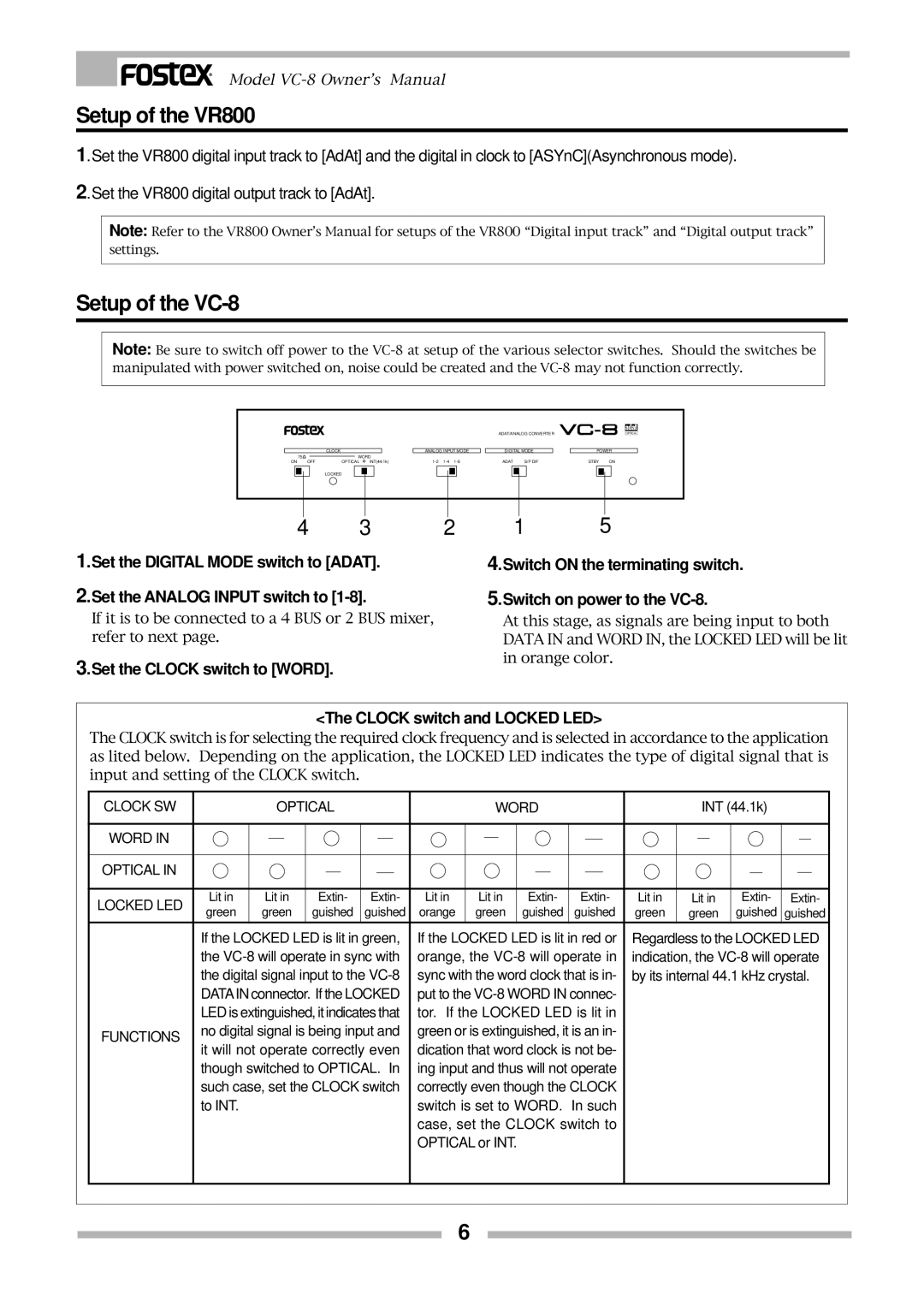
1.Set the DIGITAL MODE switch to [ADAT].
2.Set the ANALOG INPUT switch to
If it is to be connected to a 4 BUS or 2 BUS mixer, refer to next page.
3.Set the CLOCK switch to [WORD].
4.Switch ON the terminating switch.
5.Switch on power to the
At this stage, as signals are being input to both DATA IN and WORD IN, the LOCKED LED will be lit in orange color.
<The CLOCK switch and LOCKED LED>
The CLOCK switch is for selecting the required clock frequency and is selected in accordance to the application as lited below. Depending on the application, the LOCKED LED indicates the type of digital signal that is input and setting of the CLOCK switch.
CLOCK SW |
|
| OPTICAL |
|
|
|
|
| WORD |
|
|
|
|
| INT (44.1k) |
|
|
| |||||||||||||
|
|
|
|
|
|
|
|
|
|
|
|
|
|
|
|
|
|
|
|
|
|
|
|
|
|
|
|
|
|
|
|
WORD IN |
|
|
|
|
|
|
|
|
|
|
|
|
|
|
|
|
|
|
|
|
|
|
|
|
|
|
|
|
|
|
|
|
|
|
|
|
|
|
|
|
|
|
|
|
|
|
|
|
|
|
|
|
|
|
|
|
|
|
|
|
|
| |
|
|
|
|
|
|
|
|
|
|
|
|
|
|
|
|
|
|
|
|
|
|
|
|
|
|
|
|
|
|
|
|
OPTICAL IN |
|
|
|
|
|
|
|
|
|
|
|
|
|
|
|
|
|
|
|
|
|
|
|
|
|
|
|
|
|
|
|
|
|
|
|
|
|
|
|
|
|
|
|
|
|
|
|
|
|
|
|
|
|
|
|
|
|
|
|
|
|
| |
|
|
|
|
|
|
|
|
|
|
|
|
|
|
|
|
|
|
|
|
|
|
|
|
|
|
|
|
|
|
|
|
LOCKED LED | Lit in | Lit in | Extin- | Extin- | Lit in | Lit in |
| Extin- | Extin- | Lit in | Lit in | Extin- | Extin- | ||||||||||||||||||
green | green | guished | guished | orange | green |
| guished | guished | green | green | guished | guished | |||||||||||||||||||
|
| ||||||||||||||||||||||||||||||
| If the LOCKED LED is lit in green, | If the LOCKED LED is lit in red or | Regardless to the LOCKED LED | ||||||||||||||||||||||||||||
| the | orange, the | indication, the | ||||||||||||||||||||||||||||
| the digital signal input to the | sync with the word clock that is in- | by its internal 44.1 kHz crystal. | ||||||||||||||||||||||||||||
| DATAIN connector. If the LOCKED | put to the |
|
|
|
|
|
|
|
|
|
| |||||||||||||||||||
| LED is extinguished, it indicates that | tor. If the LOCKED LED is lit in |
|
|
|
|
|
|
|
|
|
| |||||||||||||||||||
FUNCTIONS | no digital signal is being input and | green or is extinguished, it is an in- |
|
|
|
|
|
|
|
|
|
| |||||||||||||||||||
it will not operate correctly even | dication that word clock is not be- |
|
|
|
|
|
|
|
|
|
| ||||||||||||||||||||
|
|
|
|
|
|
|
|
|
|
| |||||||||||||||||||||
| though switched to OPTICAL. In | ing input and thus will not operate |
|
|
|
|
|
|
|
|
|
| |||||||||||||||||||
| such case, set the CLOCK switch | correctly even though the CLOCK |
|
|
|
|
|
|
|
|
|
| |||||||||||||||||||
| to INT. |
|
|
|
|
|
|
|
|
| switch is set to WORD. In such |
|
|
|
|
|
|
|
|
|
| ||||||||||
|
|
|
|
|
|
|
|
|
|
| case, set the CLOCK switch to |
|
|
|
|
|
|
|
|
|
| ||||||||||
|
|
|
|
|
|
|
|
|
|
| OPTICAL or INT. |
|
|
|
|
|
|
|
|
|
|
|
|
|
|
|
| ||||
|
|
|
|
|
|
|
|
|
|
|
|
|
|
|
|
|
|
|
|
|
|
|
|
|
|
|
|
|
|
|
|
6