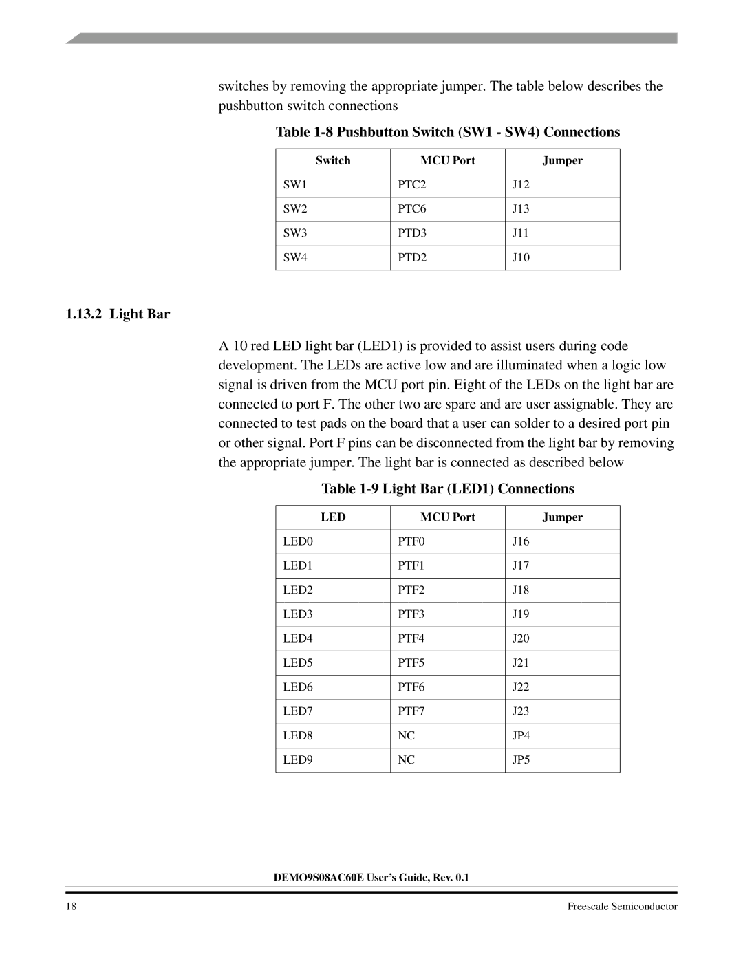
switches by removing the appropriate jumper. The table below describes the pushbutton switch connections
Table 1-8 Pushbutton Switch (SW1 - SW4) Connections
Switch | MCU Port | Jumper |
|
|
|
SW1 | PTC2 | J12 |
|
|
|
SW2 | PTC6 | J13 |
|
|
|
SW3 | PTD3 | J11 |
|
|
|
SW4 | PTD2 | J10 |
|
|
|
1.13.2 Light Bar
A 10 red LED light bar (LED1) is provided to assist users during code development. The LEDs are active low and are illuminated when a logic low signal is driven from the MCU port pin. Eight of the LEDs on the light bar are connected to port F. The other two are spare and are user assignable. They are connected to test pads on the board that a user can solder to a desired port pin or other signal. Port F pins can be disconnected from the light bar by removing the appropriate jumper. The light bar is connected as described below
Table 1-9 Light Bar (LED1) Connections
LED | MCU Port | Jumper |
|
|
|
LED0 | PTF0 | J16 |
|
|
|
LED1 | PTF1 | J17 |
|
|
|
LED2 | PTF2 | J18 |
|
|
|
LED3 | PTF3 | J19 |
|
|
|
LED4 | PTF4 | J20 |
|
|
|
LED5 | PTF5 | J21 |
|
|
|
LED6 | PTF6 | J22 |
|
|
|
LED7 | PTF7 | J23 |
|
|
|
LED8 | NC | JP4 |
|
|
|
LED9 | NC | JP5 |
|
|
|
DEMO9S08AC60E User’s Guide, Rev. 0.1
18 | Freescale Semiconductor |