Freescale Semiconductor DEMO9S08AC60E manual Integrated BDM, BDM Header, BDM Connector J32 Pinout

Models: DEMO9S08AC60E

1 24
Download 24 pages 46.63 Kb
Page 13
Image 13

1.8.1 Integrated BDM

The DEMO9S08AC60E features an integrated USB-BDM debugger from P&E Microcomputer Systems. All necessary signals are provided via the integrated debugger. A USB type B connector (J33) provides the connection between the DEMO9S08AC60E and your host PC.

The integrated debugger provides the DEMO9S08AC60E with power eliminating the need to power the board externally. Power is derived from the USB bus, therefore total current consumption should not exceed 500mA. Excessive current drain will violate the USB spec and damage to your Host PC’s USB hub or the DEMO9S08AC60E could occur.

1.8.2 BDM Header

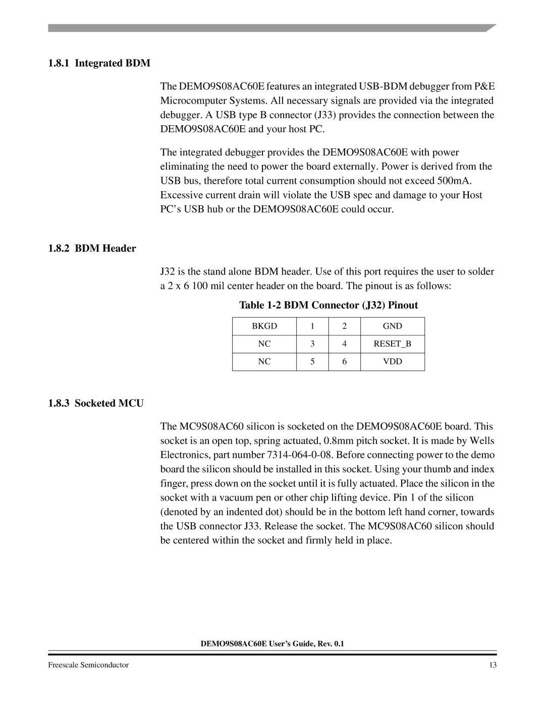
J32 is the stand alone BDM header. Use of this port requires the user to solder a 2 x 6 100 mil center header on the board. The pinout is as follows:

Table 1-2 BDM Connector (J32) Pinout

BKGD

1

2

GND


NC

3

4

RESET_B


NC

5

6

VDD


1.8.3 Socketed MCU

The MC9S08AC60 silicon is socketed on the DEMO9S08AC60E board. This socket is an open top, spring actuated, 0.8mm pitch socket. It is made by Wells Electronics, part number 7314-064-0-08. Before connecting power to the demo board the silicon should be installed in this socket. Using your thumb and index finger, press down on the socket until it is fully actuated. Place the silicon in the socket with a vacuum pen or other chip lifting device. Pin 1 of the silicon (denoted by an indented dot) should be in the bottom left hand corner, towards the USB connector J33. Release the socket. The MC9S08AC60 silicon should be centered within the socket and firmly held in place.

DEMO9S08AC60E User’s Guide, Rev. 0.1

Freescale Semiconductor

13

Page 13
Image 13
Freescale Semiconductor DEMO9S08AC60E manual Integrated BDM, BDM Header, BDM Connector J32 Pinout, Socketed MCU