Appendix
Signal Descriptions
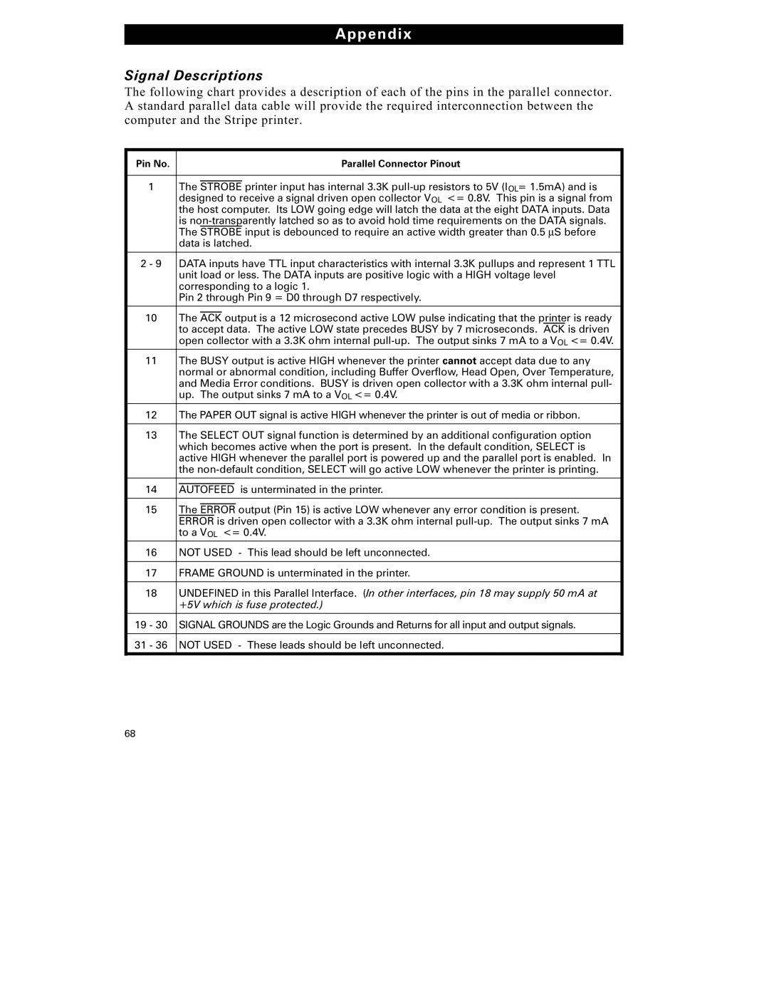
The following chart provides a description of each of the pins in the parallel connector. A standard parallel data cable will provide the required interconnection between the computer and the Stripe printer.
Pin No. |
|
|
|
|
|
| Parallel Connector Pinout |
|
|
|
|
|
|
|
|
1 |
| The |
|
|
|
| printer input has internal 3.3K |
STROBE | |||||||
|
| designed to receive a signal driven open collector VOL <= 0.8V. This pin is a signal from | |||||
|
| the host computer. Its LOW going edge will latch the data at the eight DATA inputs. Data | |||||
|
| is | |||||
|
| The STROBE input is debounced to require an active width greater than 0.5 μS before | |||||
|
| data is latched. | |||||
|
|
|
|
|
|
|
|
2 - 9 |
| DATA inputs have TTL input characteristics with internal 3.3K pullups and represent 1 TTL | |||||
|
| unit load or less. The DATA inputs are positive logic with a HIGH voltage level | |||||
|
| corresponding to a logic 1. | |||||
|
| Pin 2 through Pin 9 = D0 through D7 respectively. | |||||
|
|
|
|
|
|
|
|
10 |
| The |
| output is a 12 microsecond active LOW pulse indicating that the printer is ready | |||
ACK | |||||||
|
| to accept data. The active LOW state precedes BUSY by 7 microseconds. ACK is driven | |||||
|
| open collector with a 3.3K ohm internal | |||||
|
|
|
|
|
|
|
|
11 |
| The BUSY output is active HIGH whenever the printer cannot accept data due to any | |||||
| normal or abnormal condition, including Buffer Overflow, Head Open, Over Temperature, | ||||||
| and Media Error conditions. BUSY is driven open collector with a 3.3K ohm internal pull- | ||||||
| up. The output sinks 7 mA to a VOL <= 0.4V. | ||||||
|
|
|
|
|
|
|
|
12 |
| The PAPER OUT signal is active HIGH whenever the printer is out of media or ribbon. | |||||
|
|
|
|
|
|
|
|
13 |
| The SELECT OUT signal function is determined by an additional configuration option | |||||
|
| which becomes active when the port is present. In the default condition, SELECT is | |||||
|
| active HIGH whenever the parallel port is powered up and the parallel port is enabled. In | |||||
|
| the | |||||
|
|
|
|
|
|
|
|
14 |
|
|
| is unterminated in the printer. | |||
| AUTOFEED | ||||||
15 |
| The |
| output (Pin 15) is active LOW whenever any error condition is present. | |||
| ERROR | ||||||
|
| ERROR is driven open collector with a 3.3K ohm internal | |||||
|
| to a VOL <= 0.4V. | |||||
|
|
|
|
|
|
|
|
16 |
| NOT USED - This lead should be left unconnected. | |||||
|
|
|
|
|
|
|
|
17 |
| FRAME GROUND is unterminated in the printer. | |||||
|
|
|
|
|
|
|
|
18 |
| UNDEFINED in this Parallel Interface. (In other interfaces, pin 18 may supply 50 mA at | |||||
|
| +5V which is fuse protected.) | |||||
|
|
|
|
|
|
|
|
19 - 30 | SIGNAL GROUNDS are the Logic Grounds and Returns for all input and output signals. | ||||||
|
|
|
|
|
|
|
|
31 - 36 | NOT USED - These leads should be left unconnected. | ||||||
|
|
|
|
|
|
|
|
68