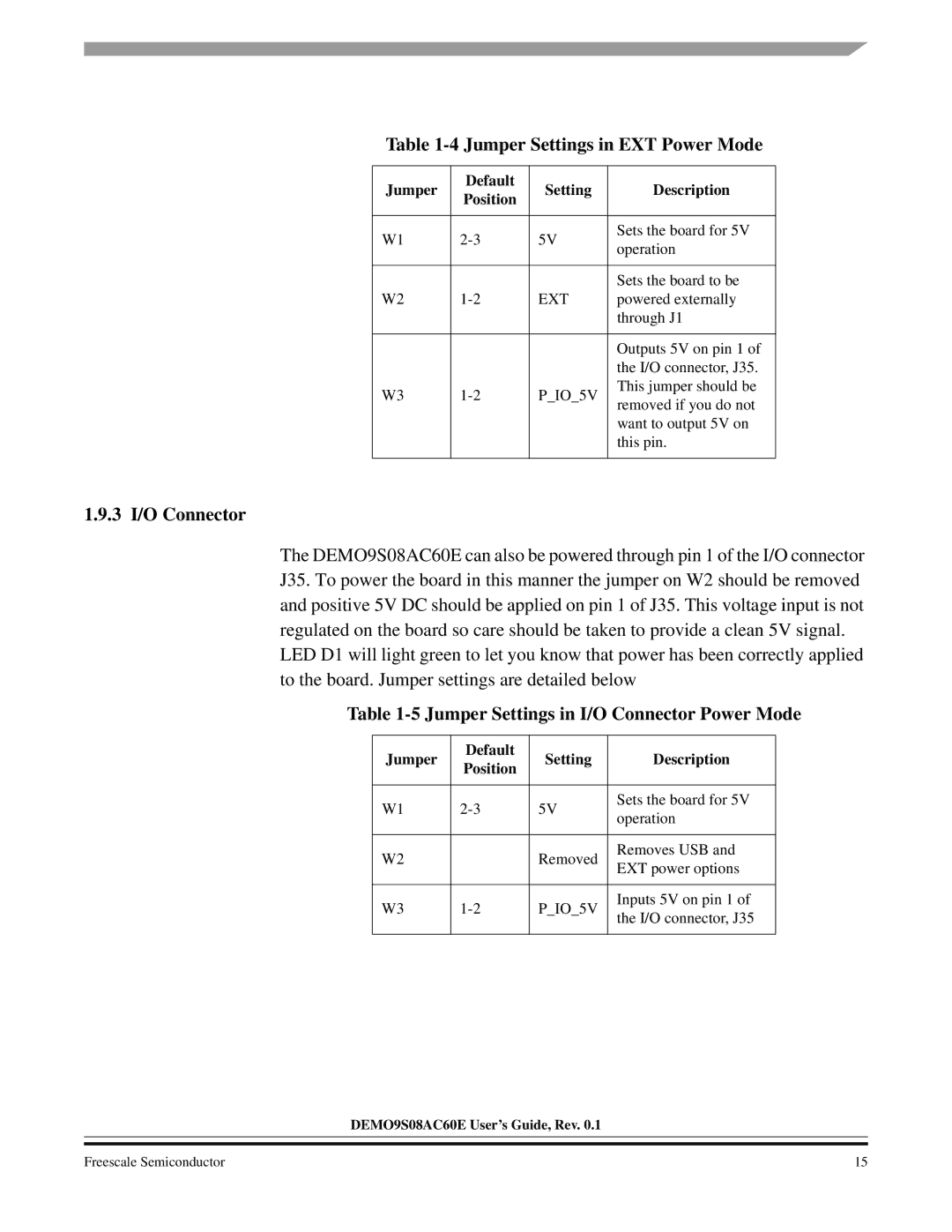
Table 1-4 Jumper Settings in EXT Power Mode
Jumper | Default | Setting | Description | |
Position | ||||
|
|
| ||
|
|
|
| |
W1 | 5V | Sets the board for 5V | ||
operation | ||||
|
|
| ||
|
|
|
| |
|
|
| Sets the board to be | |
W2 | EXT | powered externally | ||
|
|
| through J1 | |
|
|
|
| |
|
|
| Outputs 5V on pin 1 of | |
|
|
| the I/O connector, J35. | |
W3 | P_IO_5V | This jumper should be | ||
removed if you do not | ||||
|
|
| ||
|
|
| want to output 5V on | |
|
|
| this pin. | |
|
|
|
|
1.9.3 I/O Connector
The DEMO9S08AC60E can also be powered through pin 1 of the I/O connector J35. To power the board in this manner the jumper on W2 should be removed and positive 5V DC should be applied on pin 1 of J35. This voltage input is not regulated on the board so care should be taken to provide a clean 5V signal.
LED D1 will light green to let you know that power has been correctly applied to the board. Jumper settings are detailed below
Table 1-5 Jumper Settings in I/O Connector Power Mode
Jumper | Default | Setting | Description | |
Position | ||||
|
|
| ||
|
|
|
| |
W1 | 5V | Sets the board for 5V | ||
operation | ||||
|
|
| ||
|
|
|
| |
W2 |
| Removed | Removes USB and | |
| EXT power options | |||
|
|
| ||
|
|
|
| |
W3 | P_IO_5V | Inputs 5V on pin 1 of | ||
the I/O connector, J35 | ||||
|
|
| ||
|
|
|
|
DEMO9S08AC60E User’s Guide, Rev. 0.1
Freescale Semiconductor | 15 |