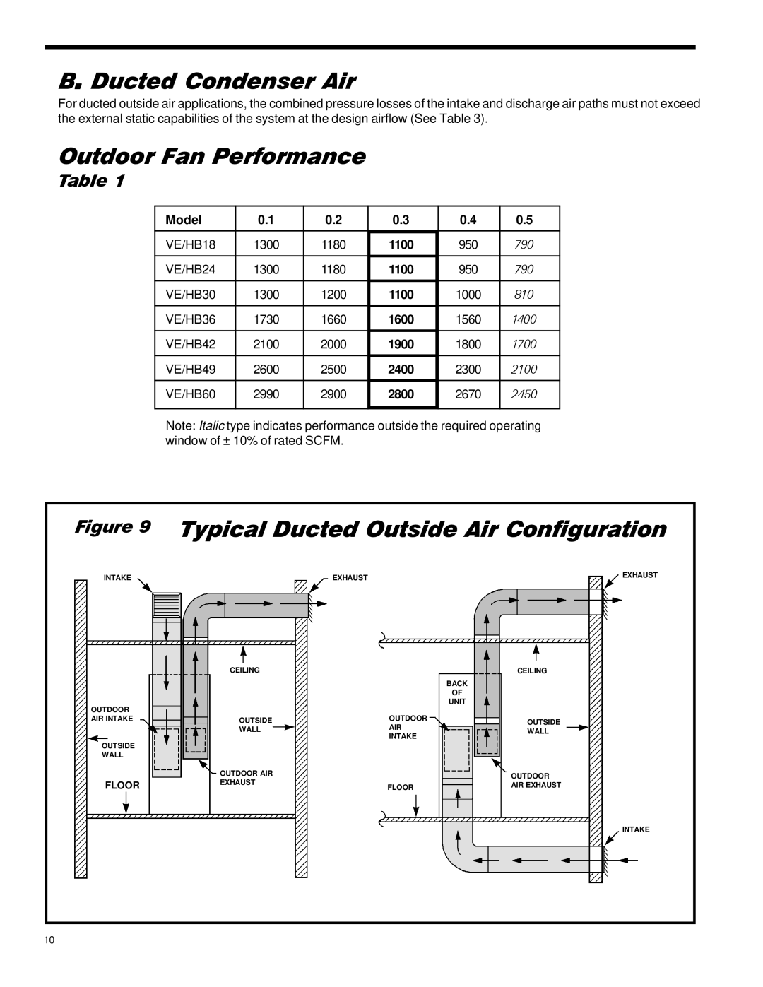
B. Ducted Condenser Air
For ducted outside air applications, the combined pressure losses of the intake and discharge air paths must not exceed the external static capabilities of the system at the design airflow (See Table 3).
Outdoor Fan Performance
Table 1
Model | 0.1 | 0.2 | 0.3 | 0.4 | 0.5 |
|
|
|
|
|
|
VE/HB18 | 1300 | 1180 | 1100 | 950 | 790 |
|
|
|
|
|
|
VE/HB24 | 1300 | 1180 | 1100 | 950 | 790 |
|
|
|
|
|
|
VE/HB30 | 1300 | 1200 | 1100 | 1000 | 810 |
|
|
|
|
|
|
VE/HB36 | 1730 | 1660 | 1600 | 1560 | 1400 |
|
|
|
|
|
|
VE/HB42 | 2100 | 2000 | 1900 | 1800 | 1700 |
|
|
|
|
|
|
VE/HB49 | 2600 | 2500 | 2400 | 2300 | 2100 |
|
|
|
|
|
|
VE/HB60 | 2990 | 2900 | 2800 | 2670 | 2450 |
|
|
|
|
|
|
Note: Italic type indicates performance outside the required operating window of ± 10% of rated SCFM.
Figure 9 | Typical Ducted Outside Air Configuration | |||
INTAKE |
| EXHAUST | EXHAUST | |
|
| |||
| CEILING |
| CEILING | |
|
|
| BACK | |
|
|
| OF | |
OUTDOOR |
|
| UNIT | |
| OUTDOOR |
| ||
AIR INTAKE | OUTSIDE | OUTSIDE | ||
| WALL | AIR | WALL | |
| INTAKE | |||
|
|
| ||
OUTSIDE |
|
|
| |
WALL |
|
|
| |
| OUTDOOR AIR |
| OUTDOOR | |
FLOOR | EXHAUST |
| ||
FLOOR | AIR EXHAUST | |||
| ||||
INTAKE
10
