3)THERMOSTAT MOUNTING AND WIRING A. Thermostat Location
Locate the thermostat about 5 ft. above the floor in an area with good circulation at average indoor temperature.
Do not mount the thermostat where it may be affected by:
•Drafts or
•Hot or cold air flow from ducts.
•Radiant heat from sun or appliances.
•Concealed pipes or chimneys.
•Unheated (uncooled) areas behind thermostat, such as an outside wall.
B. Thermostat Mounting and Wiring
The thermostat is a precision instrument and was carefully adjusted at the factory. Handle it carefully.
![]() CAUTION: Disconnect the power supply before beginning installation of the thermostat to prevent electrical shock or equipment damage. Do not short across the thermostat terminals. This can burn out the thermostat anticipator.
CAUTION: Disconnect the power supply before beginning installation of the thermostat to prevent electrical shock or equipment damage. Do not short across the thermostat terminals. This can burn out the thermostat anticipator.
All wiring for the thermostat circuit must comply with NEC, state and local codes. Use No. 20 AWG
1.In replacement applications, check the existing thermostat wiring for cracked or frayed insulation. Replace any wiring in poor condition. All wiring must comply with local codes and ordinances.
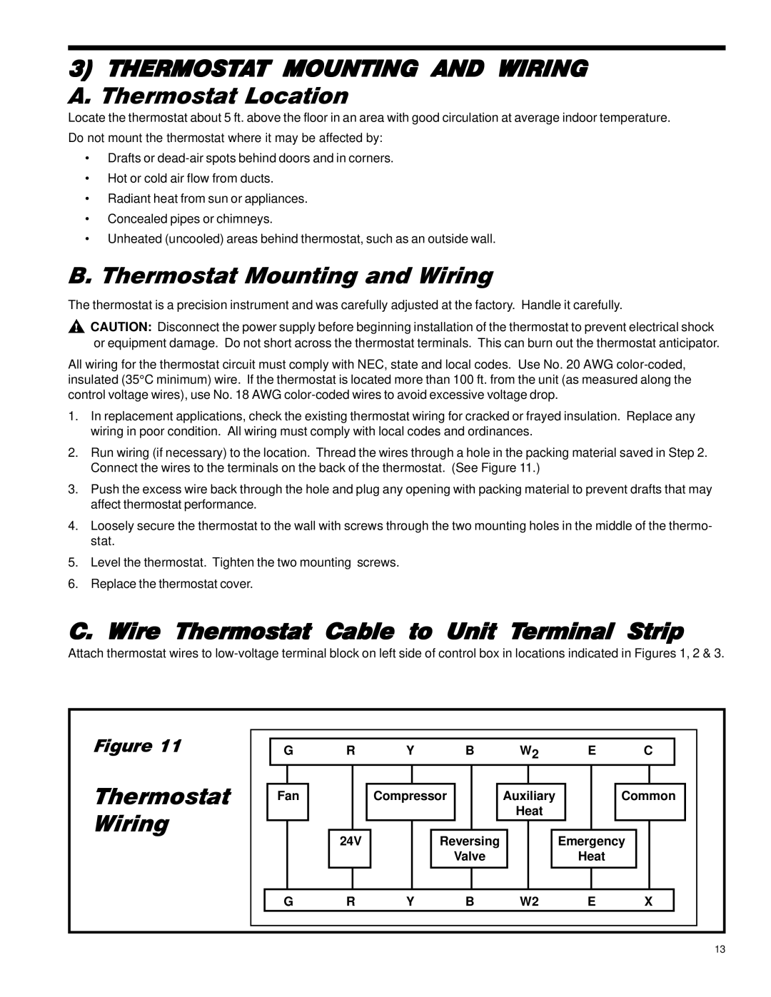
2.Run wiring (if necessary) to the location. Thread the wires through a hole in the packing material saved in Step 2. Connect the wires to the terminals on the back of the thermostat. (See Figure 11.)
3.Push the excess wire back through the hole and plug any opening with packing material to prevent drafts that may affect thermostat performance.
4.Loosely secure the thermostat to the wall with screws through the two mounting holes in the middle of the thermo- stat.
5.Level the thermostat. Tighten the two mounting screws.
6.Replace the thermostat cover.
C. Wire Thermostat Cable to Unit Terminal Strip
Attach thermostat wires to
Figure 11
Thermostat Wiring
| G |
| R |
| Y |
| B |
| W2 |
| E |
| C |
| |||||||||
|
|
|
|
|
|
|
|
|
|
|
|
|
|
|
|
|
|
|
|
|
|
|
|
| Fan |
|
|
|
| Compressor |
|
|
| Auxiliary |
|
|
| Common | |||||||||
|
|
|
|
|
|
|
|
|
|
|
|
|
| Heat |
|
|
|
|
|
|
| ||
|
|
|
|
|
|
|
|
|
|
|
|
|
|
|
|
|
|
|
|
|
|
|
|
|
|
|
|
|
|
|
|
|
|
|
|
|
|
|
|
|
|
|
| ||||
|
|
|
| 24V |
|
|
| Reversing |
|
|
|
| Emergency |
|
|
| |||||||
|
|
|
|
|
|
|
|
| Valve |
|
|
|
|
| Heat |
|
|
|
| ||||
|
|
|
|
|
|
|
|
|
|
|
|
|
|
|
|
|
|
|
|
|
|
|
|
|
|
|
|
|
|
|
|
|
|
|
|
|
|
|
|
|
|
|
|
|
|
|
|
G | R | Y | B | W2 | E | X |
|
|
|
|
|
|
|
13