2) Electrical
DANGER: Electrical shock hazard. Turn OFF electric power at the fuse box or service panel before making any electrical connections and ensure a proper ground connection is made before connecting line voltage. Failure to do so can result in property damage, personal injury and/or death.
A. Grounding
![]() CAUTION: The unit must be electrically wired and grounded in accordance with all state and local codes, national electric code, and NFPA 70. Unit and controls will NOT operate unless properly grounded. A ground lug is provided for ground connection. Use only approved copper wire and connectors from unit to service panel.
CAUTION: The unit must be electrically wired and grounded in accordance with all state and local codes, national electric code, and NFPA 70. Unit and controls will NOT operate unless properly grounded. A ground lug is provided for ground connection. Use only approved copper wire and connectors from unit to service panel.
B. Power Supply
NOTE: Line voltage circuit is completely factory wired. Make all line voltage connections inside circuit breaker junction box. The circuit breakers or fuses used for branch circuit protection should be UL recognized. If circuit breakers are used, the circuit breaker for the compressor circuit must have a UL HACR rating. If fuses are used, the fuse for the compressor circuit MUST be time delay type.
![]() CAUTION: Units are dual voltage rated
CAUTION: Units are dual voltage rated
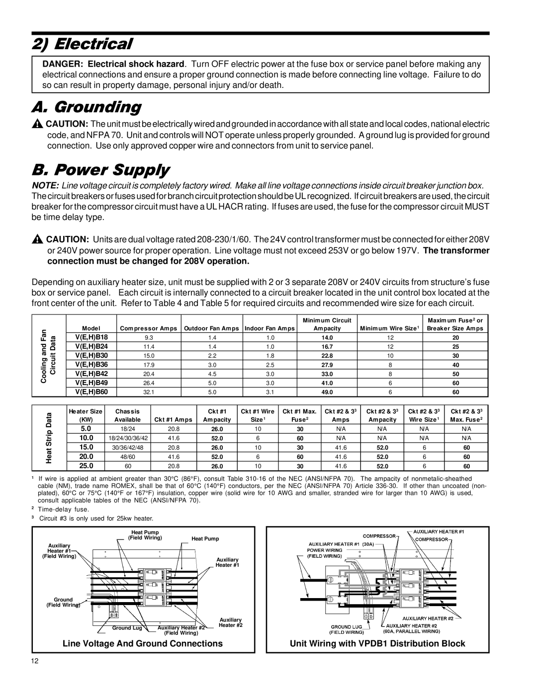
Depending on auxiliary heater size, unit must be supplied with 2 or 3 separate 208V or 240V circuits from structure’s fuse box or service panel. Each circuit is internally connected to a circuit breaker located in the unit control box located at the front center of the unit. Refer to Table 4 and Table 5 for required circuits and recommended wire size for each circuit.
|
|
|
|
|
|
|
|
|
|
|
|
|
| Minim um Circuit |
|
|
| Maxim um Fuse2 or | ||
Cooling and Fan |
| Model |
| Com pressor Am ps | Outdoor Fan Am ps |
| Indoor Fan Am ps | Am pacity | Minim um Wire Size 1 | Breaker Size Am ps | ||||||||||
Circuit Data | V(E,H)B18 |
| 9.3 |
|
| 1.4 |
|
| 1.0 |
|
| 14.0 | 12 |
|
| 20 | ||||
V(E,H)B24 |
| 11.4 |
| 1.4 |
|
| 1.0 |
|
| 16.7 | 12 |
|
| 25 | ||||||
V(E,H)B30 |
| 15.0 |
| 2.2 |
|
| 1.8 |
|
| 22.8 | 10 |
|
| 30 | ||||||
V(E,H)B36 |
| 17.9 |
| 3.0 |
|
| 2.5 |
|
| 27.9 | 8 |
|
| 40 | ||||||
V(E,H)B42 |
| 20.4 |
| 4.5 |
|
| 3.0 |
|
| 33.0 | 8 |
|
| 50 | ||||||
| V(E,H)B49 |
| 26.4 |
| 5.0 |
|
| 3.0 |
|
| 41.0 | 6 |
|
| 60 | |||||
|
|
|
|
|
|
|
|
|
| |||||||||||
|
| V(E,H)B60 |
| 32.1 |
| 5.0 |
|
| 3.1 |
|
| 49.0 | 6 |
|
| 60 | ||||
|
|
|
|
|
|
|
|
|
|
|
|
|
|
|
|
| ||||
| Data | Heater Size |
| Chassis |
|
|
| Ckt #1 |
| Ckt #1 Wire | Ckt #1 Max. | Ckt #2 & 33 |
| Ckt #2 & 33 | Ckt #2 & 33 | Ckt #2 & 33 | ||||
| (KW) |
| Available |
| Ckt #1 Am ps | Am pacity |
|
| Size1 | Fuse2 | Am ps |
| Am pacity | Wire Size 1 | Max. Fuse2 | |||||
| 5.0 |
| 18/24 |
| 20.8 |
| 26.0 |
| 10 |
| 30 | N/A |
| N/A | N/A | N/A | ||||
| Strip |
|
|
|
|
|
| |||||||||||||
| 10.0 |
| 18/24/30/36/42 |
| 41.6 |
| 52.0 |
| 6 |
| 60 | N/A |
| N/A | N/A | N/A | ||||
| 15.0 |
| 30/36/42/48 |
| 20.8 |
| 26.0 |
| 10 |
| 30 | 41.6 |
| 52.0 | 6 | 60 | ||||
| Heat |
|
|
|
|
|
| |||||||||||||
| 20.0 |
| 48/60 |
| 41.6 |
| 52.0 |
| 6 |
| 60 | 41.6 |
| 52.0 | 6 | 60 | ||||
| 25.0 |
| 60 |
| 20.8 |
| 26.0 |
| 10 |
| 30 | 41.6 |
| 52.0 | 6 | 60 | ||||
|
|
|
|
|
|
|
| |||||||||||||
1If wire is applied at ambient greater than 30°C (86°F), consult Table
2
3Circuit #3 is only used for 25kw heater.
Heat Pump |
|
(Field Wiring) | Heat Pump |
Auxiliary
Heater #1
(Field Wiring)
Auxiliary
Heater #1
Ground |
|
|
|
(Field Wiring) |
|
|
|
|
| Auxiliary |
|
Ground Lug | Auxiliary Heater #2 | Heater #2 |
|
|
| ||
| (Field Wiring) |
|
|
Line Voltage And Ground Connections | Unit Wiring with VPDB1 Distribution Block | ||
12