UHC-HD specifications
The Frymaster UHC-HD is a high-performance commercial fryer designed to meet the demanding needs of modern kitchens. Key to its appeal is the innovative Ultra High Efficiency (UHC) technology, which allows this fryer to achieve exceptional cooking results while minimizing energy consumption. The UHC-HD model is built for efficiency, making it an ideal choice for busy restaurants, fast-food establishments, and other foodservice operations.One of the standout features of the Frymaster UHC-HD is its dual-zone frying capability. This design facilitates optimal cooking by allowing users to cook multiple products simultaneously while maintaining the integrity of flavors. With the ability to manage separate oil zones, operators can minimize flavor transfer, ensuring that chicken doesn't taste like fish and vice versa. This feature is particularly beneficial during peak hours when demand for diverse menu items is high.
Additionally, the Frymaster UHC-HD is equipped with a state-of-the-art filtration system that enhances oil life and improves food quality. This built-in filtration system continuously circulates and filters the oil, removing impurities and extending its usability, resulting in cost savings on oil purchases and reduced waste. The fryer also features a simple, intuitive user interface that provides operators with real-time data on oil quality and temperature, allowing for precise control over the frying process.
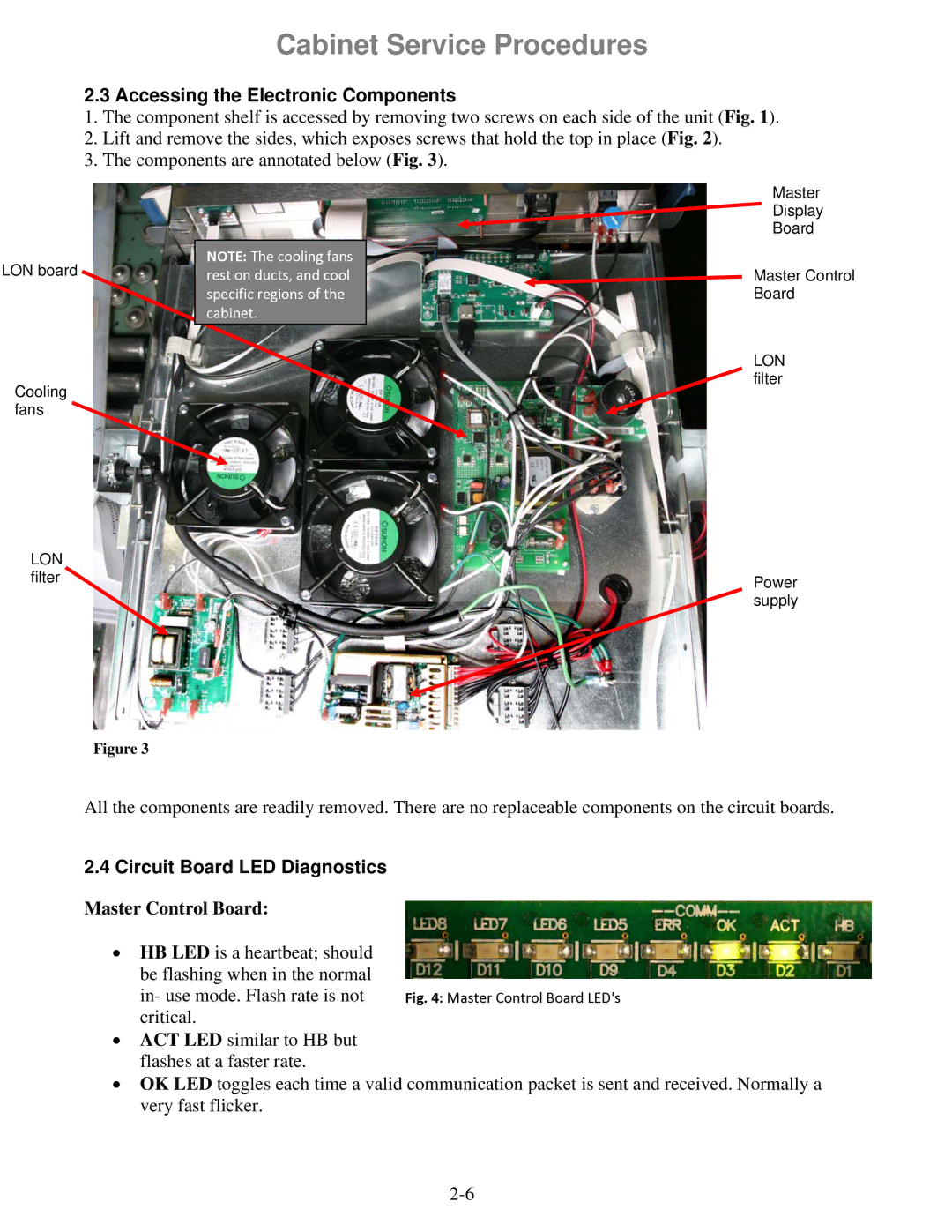
Another significant benefit of the UHC-HD is its durability and ease of maintenance. Constructed from high-quality materials, this fryer is designed to withstand the rigors of daily use. The fryer’s design allows for easy access to components, making routine cleaning and maintenance straightforward. This focus on durability not only enhances the fryer’s lifespan but also helps ensure consistent cooking performance.
The Frymaster UHC-HD also incorporates advanced safety features. The enhanced safety mechanisms include temperature limiters and automatic shut-off functionalities, which minimize the risk of overheating and accidents in the kitchen. This attention to safety is critical in fast-paced cooking environments where operators must prioritize efficiency without compromising on safety.
In conclusion, the Frymaster UHC-HD stands out as a premier choice for anyone looking to elevate their frying capabilities. With its innovative technology, energy-saving design, and user-friendly features, it is a perfect fit for a variety of foodservice applications. Whether frying a batch of crispy chicken or perfectly golden fries, the UHC-HD combines performance and efficiency, making every frying experience exceptional.

