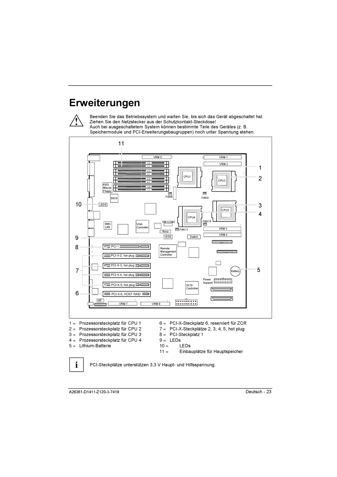
Erweiterungen
Beenden Sie das Betriebssystem und warten Sie, bis sich das Gerät abgeschaltet hat. ! Ziehen Sie den Netzstecker aus der
Auch bei ausgeschaltetem System können bestimmte Teile des Gerätes (z. B. Speichermodule und
|
| 11 |
|
|
|
|
|
|
|
|
|
| VRM 5 |
|
| VRM 1 |
|
|
|
| 4.2 |
|
|
| VRM 2 | 1 |
|
|
| 4.1 |
|
|
| ||
|
|
|
|
|
|
| ||
|
|
| 3.2 |
|
|
|
| |
|
|
| 3.1 |
|
| CPU1 |
| 2 |
|
|
| 2.2 |
|
|
| ||
|
|
|
|
|
| CPU2 | ||
| KBD |
| 2.1 |
|
|
| ||
|
| 1.2 |
|
|
|
|
| |
| Mouse |
|
|
|
|
| ||
| 1.1 |
|
|
|
|
| ||
| Floppy |
|
|
|
|
| ||
|
|
|
|
|
|
| ||
| BIOS |
| FAN8 | FAN9 |
|
| ||
|
|
|
|
|
| |||
10 | LEDS |
|
|
|
|
|
| 3 |
|
|
|
|
|
| CPU3 | ||
|
|
|
|
|
|
| 4 | |
|
|
|
|
|
| CPU4 |
| |
|
|
|
|
|
|
|
| |
| BMC | VGA |
| FAN10 |
|
| ||
|
|
|
|
|
|
| ||
| LAN | Controller |
|
| FAN11 | VRM 3 |
| |
|
|
|
| Accu |
|
| ||
|
|
|
|
|
|
| ||
|
|
|
|
|
| VRM 4 |
| |
9 |
|
|
| LEDS | Switch |
| ||
|
|
|
|
| ||||
|
|
|
|
|
|
|
| |
8 |
| PCI 1 |
| Remote |
|
|
| |
|
|
|
|
|
| |||
|
|
|
| Management |
|
|
| |
|
| Controller |
|
|
| |||
7 |
|
|
|
|
| 5 | ||
|
|
|
| Battery | ||||
|
|
|
|
|
|
| ||
|
|
|
|
|
| Power |
|
|
|
|
|
|
| Support |
|
| |
|
|
|
|
| SCSI |
|
| |
6 |
|
|
|
|
| Controller |
|
|
|
|
|
|
|
|
| ||
| HP | VRM 7 |
| VRM 6 |
|
|
|
|
|
|
|
|
|
|
| ||
1 = Prozessorsteckplatz für CPU 1 |
| 6 = |
| |||||
2 = Prozessorsteckplatz für CPU 2 |
| 7 = |
| |||||
3 = Prozessorsteckplatz für CPU 3 |
| 8 = |
|
| ||||
4 = Prozessorsteckplatz für CPU 4 |
| 9 = | LEDs |
|
| |||
5 = |
|
| 10 = |
| LEDs |
|
| |
|
|
|
| 11 = |
| Einbauplätze für Hauptspeicher |
| |
i |
| |
|
| |
Deutsch - 23 | ||
