|
| System configurator and | |
|
| PRIMERGY TX150 S4 | Status 25.11.2005 |
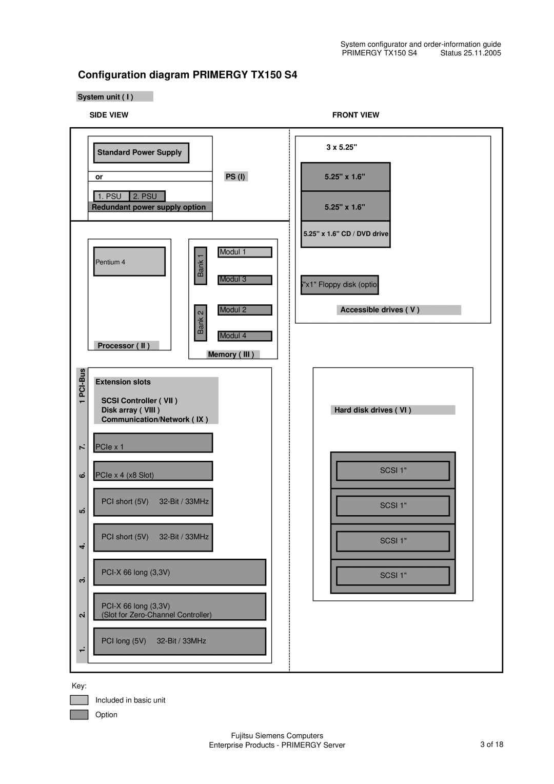
Configuration diagram PRIMERGY TX150 S4 |
|
| |
|
|
| |
System unit ( I ) |
|
|
|
SIDE VIEW | FRONT VIEW |
| |
| Standard Power Supply |
|
|
| ||
|
|
|
|
|
|
|
|
|
|
|
|
|
|
| or |
|
|
|
| PS (I) |
|
|
|
|
|
|
|
| 1. PSU | 2. PSU |
|
|
|
|
Redundant power supply option
3 x 5.25"
5.25" x 1.6"
5.25" x 1.6"
5.25" x 1.6" CD / DVD drive
Pentium 4
Processor ( II )
Bank 1 | Modul 1 | |
Modul 3 | ||
| ||
Bank 2 | Modul 2 | |
Modul 4 | ||
|
Memory ( III )
5"x1" Floppy disk (optio
Accessible drives ( V )
1 PCI-Bus
1. 2. 3. 4. 5. 6. 7.
Extension slots
SCSI Controller ( VII ) Disk array ( VIII ) Communication/Network ( IX )
PCIe x 1
PCIe x 4 (x8 Slot)
PCI short (5V) | |
|
|
|
|
PCI short (5V) | |
|
|
(Slot for
PCI long (5V)
Hard disk drives ( VI )
SCSI 1"
SCSI 1"
SCSI 1"
SCSI 1"
Key:
Included in basic unit
Option
Fujitsu Siemens Computers | 3 of 18 |
Enterprise Products - PRIMERGY Server |