
MODEL CSH-73 specifications
The Furuno MODEL CSH-73 is a cutting-edge marine radar that embodies innovative technology and exceptional performance, designed specifically for commercial vessels and professional mariners. This model represents a significant advancement in radar capabilities, enhancing both navigational safety and operational efficiency.One of the standout features of the CSH-73 is its compact design paired with a high-resolution display. The radar boasts a 12.1-inch color LCD screen that provides a crisp and clear view, allowing operators to easily identify targets and navigate in challenging conditions. The intuitive user interface facilitates quick access to essential radar functions, making it user-friendly even for those who may not be experts in radar operation.
A notable technological advancement in the CSH-73 is its digital signal processing (DSP) technology, which dramatically improves target detection capabilities, especially in adverse weather conditions. This technology helps to filter out noise and clutter, enabling the radar to provide accurate readings and reliable targeting information. The advanced target tracking capabilities allow users to monitor multiple vessels simultaneously, enhancing situational awareness.
In addition to its impressive detection capabilities, the CSH-73 features an Automatic Radar Plotting Aid (ARPA), which aids in collision avoidance by tracking the course and speed of approaching vessels. This sophisticated system simplifies decision-making for the crew, promoting safer navigation.
Another key innovation is the integration of Ethernet and NMEA 2000 connectivity. This feature enables seamless integration with other onboard systems, such as chart plotters and autopilots, creating a comprehensive navigation network. This connectivity allows for real-time data sharing, which enhances the overall operational effectiveness of the vessel.
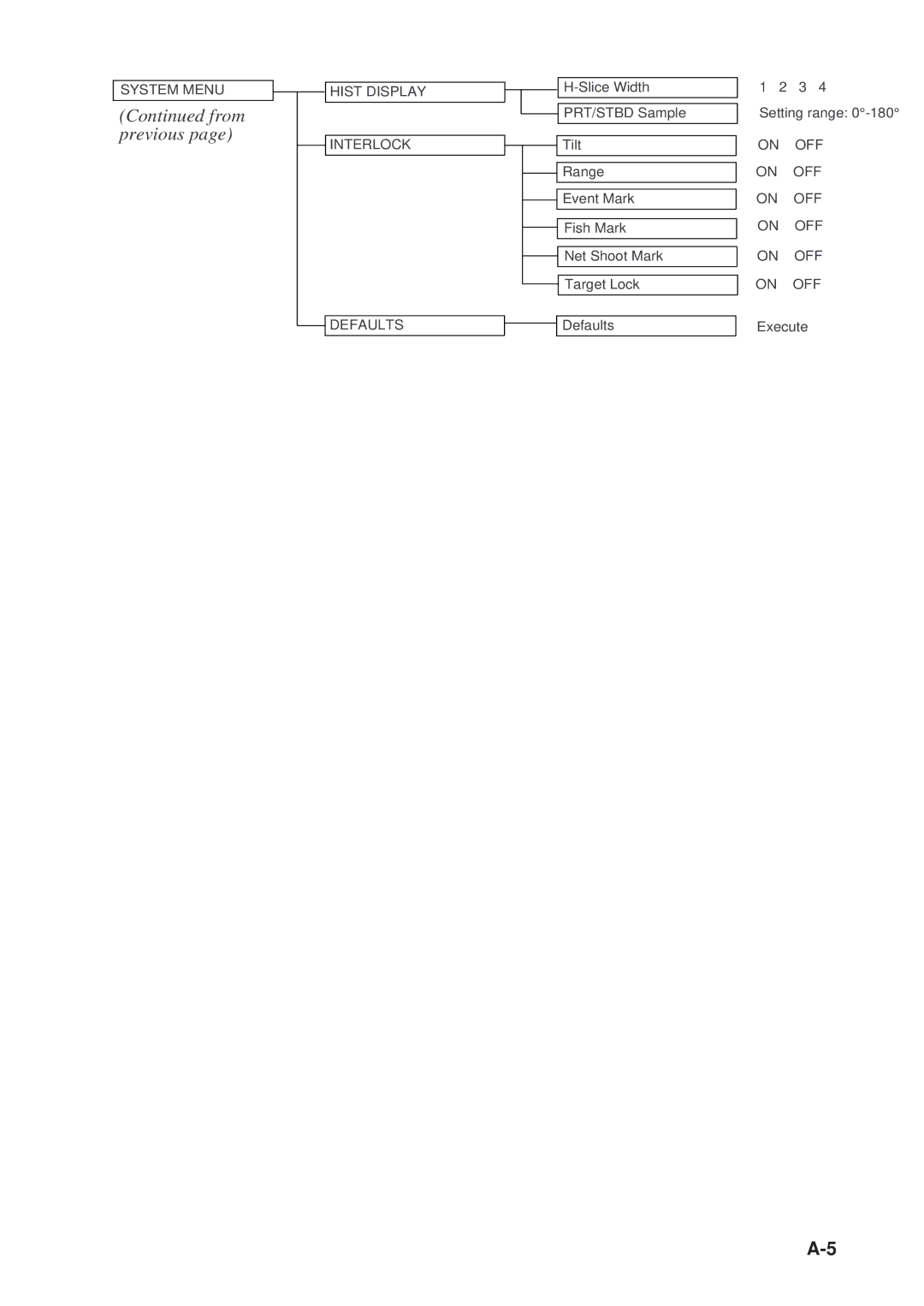
The CSH-73 is also equipped with a range of customizable settings, allowing mariners to tailor the radar display to their specific needs and preferences. Features such as adjustable gain, sea clutter, and rain clutter suppression enhance the radar's performance under various environmental conditions.
Constructed with durability in mind, the CSH-73 adheres to robust marine standards, ensuring reliable performance even in the harshest maritime environments. This resilience is crucial for commercial vessels that regularly operate in challenging conditions.
In summary, the Furuno MODEL CSH-73 stands out as a powerful tool for enhancing maritime safety and navigation. Its advanced technologies, user-friendly interface, and durable construction make it an essential component for modern vessels, providing mariners with the confidence they need to operate effectively in any navigational scenario. The CSH-73 continues to uphold Furuno's reputation for excellence in marine electronics, making it a trusted choice for professionals worldwide.