ELECTRICAL CONNECTION DETAILS
OBSERVE ALL GOVERNING CODES AND ORDINANCES
GROUNDING INSTRUCTIONS
The operating voltage (Volts), Amperage (Amps) and Frequency | This appliance must be grounded. In the | event of malfunction or | ||
(Hz) of this dryer are indicated on the Rating Plate located to the | ||||
breakdown, grounding will reduce the risk of | electric shock by providing | |||
right of the loading port. | ||||
a path of least resistance for electrical current. | ||||
Connect this dryer to a circuit corresponding to that indicated on | ||||
WARNING: Improper connection of the equipment grounding conductor | ||||
rating plate and protected by fuses or a circuit breaker | ||||
can result in a risk of electric shock. Check with a qualified electrician | ||||
in accordance with local codes. | ||||
Use a power supply cord kit marked for use with clothes dryer. | or serviceman if you are in doubt as to whether the appliance is | |||
For 208V and 240V models, use a power supply cord kit marked for use | properly grounded. |
| ||
with clothes dryers. | Do not modify the plug provided with the appliance - if it will not fit the | |||
DO NOT USE EXTENSION CORD WITH THIS APPLIANCE |
| outlet, have a proper outlet installed by a qualified electrician. | ||
For alternate 208V or 240V power supply
![]() Remove rear access panel.
Remove rear access panel.
![]() Connect supply wire leads to terminal block as shown on sketch below, depending on type of installation.
Connect supply wire leads to terminal block as shown on sketch below, depending on type of installation.
WARNING: Appliance grounded to neutral conductor through a link. If used in a mobile home or if local codes do not permit grounding through neutral, a
Make sure screws on terminal block are tight.
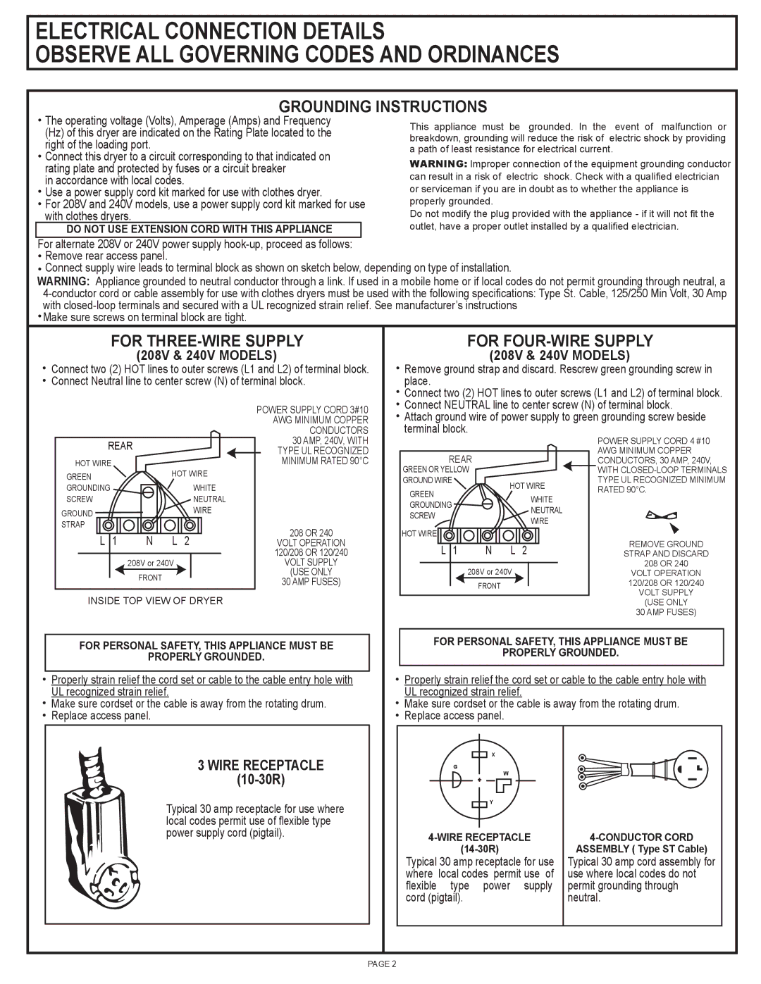
FOR THREE-WIRE SUPPLY
(208V & 240V MODELS)
![]() Connect two (2) HOT lines to outer screws (L1 and L2) of terminal block.
Connect two (2) HOT lines to outer screws (L1 and L2) of terminal block. ![]() Connect Neutral line to center screw (N) of terminal block.
Connect Neutral line to center screw (N) of terminal block.
FOR FOUR-WIRE SUPPLY
(208V & 240V MODELS)
![]() Remove ground strap and discard. Rescrew green grounding screw in place.
Remove ground strap and discard. Rescrew green grounding screw in place.
![]() Connect two (2) HOT lines to outer screws (L1 and L2) of terminal block.
Connect two (2) HOT lines to outer screws (L1 and L2) of terminal block.
Connect NEUTRAL line to center screw (N) of terminal block.
POWER SUPPLY CORD 3#10
AWG MINIMUM COPPER CONDUCTORS
![]() Attach ground wire of power supply to green grounding screw beside terminal block.
Attach ground wire of power supply to green grounding screw beside terminal block.
REAR |
|
| ||
HOT WIRE |
|
| HOT WIRE | |
GREEN |
|
| ||
|
|
|
| |
GROUNDING |
|
|
| WHITE |
SCREW |
|
|
| NEUTRAL |
GROUND |
|
|
| WIRE |
|
|
|
| |
STRAP |
|
|
|
|
L | 1 | N | L | 2 |
|
| 208V or 240V |
| |
|
| FRONT |
|
|
30 AMP, 240V, WITH TYPE UL RECOGNIZED MINIMUM RATED 90°C
208 OR 240
VOLT OPERATION 120/208 OR 120/240
VOLT SUPPLY
(USE ONLY
30 AMP FUSES)
REAR |
|
|
| |
GREEN OR YELLOW |
|
|
| |
GROUND WIRE |
|
| HOT WIRE | |
GREEN |
|
| ||
|
|
| WHITE | |
GROUNDING |
|
|
| |
|
|
| NEUTRAL | |
SCREW |
|
|
| |
|
|
| WIRE | |
|
|
|
| |
HOT WIRE |
|
|
|
|
L | 1 | N | L | 2 |
| 208V or 240V |
| ||
|
| FRONT |
|
|
POWER SUPPLY CORD 4 #10
AWG MINIMUM COPPER CONDUCTORS, 30 AMP, 240V,
WITH
REMOVE GROUND
STRAP AND DISCARD
208 OR 240
VOLT OPERATION 120/208 OR 120/240
VOLT SUPPLY
INSIDE TOP VIEW OF DRYER
FOR PERSONAL SAFETY, THIS APPLIANCE MUST BE
PROPERLY GROUNDED.
![]() Properly strain relief the cord set or cable to the cable entry hole with UL recognized strain relief.
Properly strain relief the cord set or cable to the cable entry hole with UL recognized strain relief.
![]() Make sure cordset or the cable is away from the rotating drum.
Make sure cordset or the cable is away from the rotating drum.
![]() Replace access panel.
Replace access panel.
(USE ONLY
30 AMP FUSES)
FOR PERSONAL SAFETY, THIS APPLIANCE MUST BE
PROPERLY GROUNDED.
![]() Properly strain relief the cord set or cable to the cable entry hole with UL recognized strain relief.
Properly strain relief the cord set or cable to the cable entry hole with UL recognized strain relief.
![]() Make sure cordset or the cable is away from the rotating drum.
Make sure cordset or the cable is away from the rotating drum.
![]() Replace access panel.
Replace access panel.
3 WIRE RECEPTACLE
(10-30R)
Typical 30 amp receptacle for use where local codes permit use of flexible type power supply cord (pigtail).
X
G
W
Y
Typical 30 amp receptacle for use where local codes permit use of flexible type power supply cord (pigtail).
ASSEMBLY ( Type ST Cable)
Typical 30 amp cord assembly for use where local codes do not permit grounding through neutral.
PAGE 2