Electrical Connection
We recommend that you have the electrical hookup of your range done by a qualified electrician. Have the electrician show you where your range disconnect is located.
Call your Electric Company and ask which codes apply in your area. If there are no codes, you must follow the NATIONAL ELECI’RICAL CODE, ANSI/NFPA NO.
National Fire Protection Association
Batterymarch Park
Quincy, MA 02269
If you fail to wire your range in accordance with governing codes, you may create a hazardous condition.
You must use a
Use #8 wire and 40 Amp fuse or circuit breaker for 120/240 Volt and 208/120 Volt systems.
Do not use aluminum wiring to connect your range to the household circuit.
To Make Electrical Connection:
1.Remove the junction block access cover (on range back).
2.Use a
You must use the strain relief clamp provided with the range to hold the cord.
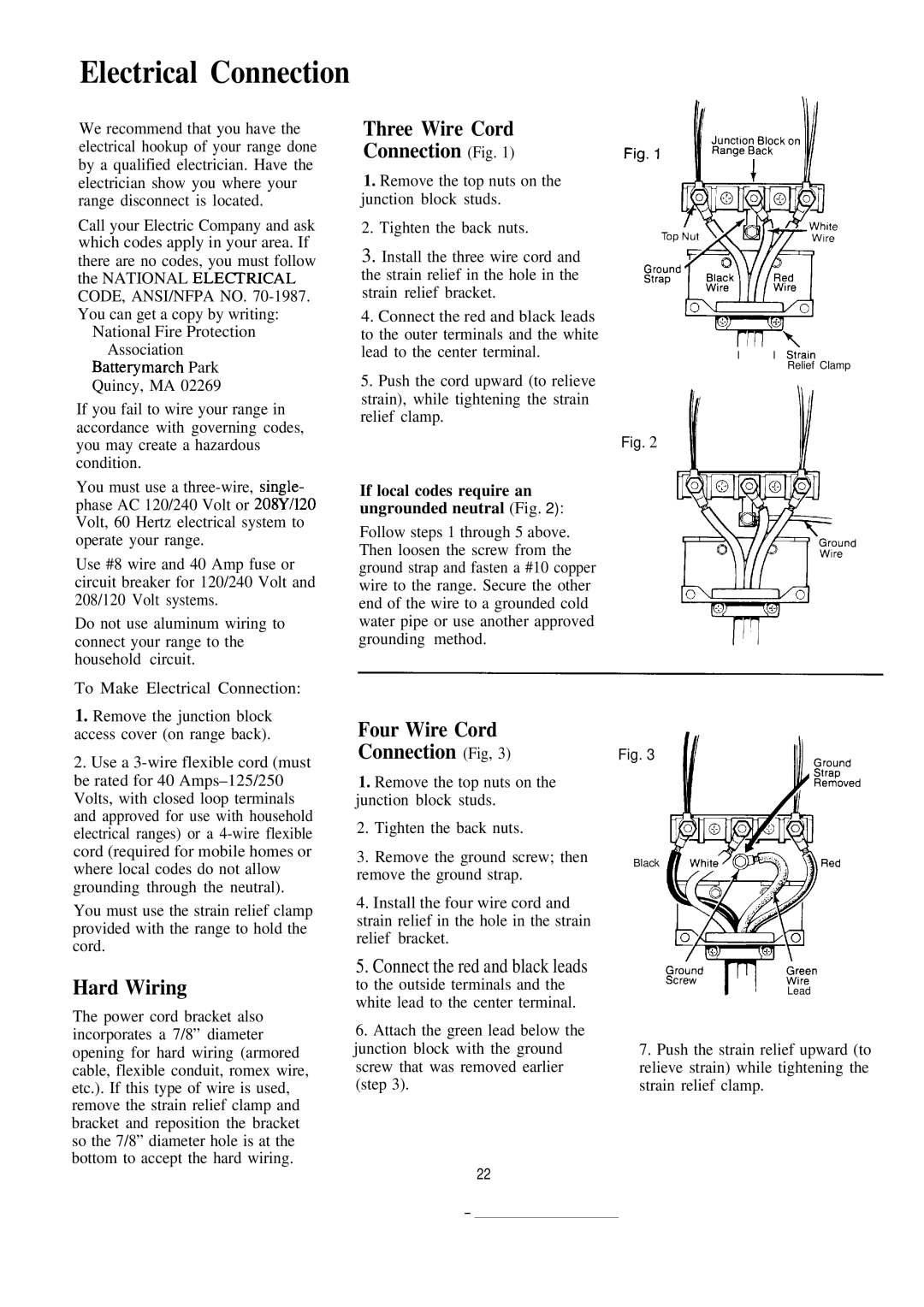
Three Wire Cord
Connection (Fig. 1)
1.Remove the top nuts on the junction block studs.
2.Tighten the back nuts.
3.Install the three wire cord and the strain relief in the hole in the strain relief bracket.
4.Connect the red and black leads to the outer terminals and the white lead to the center terminal.
5.Push the cord upward (to relieve strain), while tightening the strain relief clamp.
If local codes require an ungrounded neutral (Fig. 2):
Follow steps 1 through 5 above. Then loosen the screw from the ground strap and fasten a #10 copper wire to the range. Secure the other end of the wire to a grounded cold water pipe or use another approved grounding method.
Four Wire Cord
Connection (Fig, 3)
1.Remove the top nuts on the junction block studs.
2.Tighten the back nuts.
3.Remove the ground screw; then remove the ground strap.
4.Install the four wire cord and strain relief in the hole in the strain relief bracket.
I ‘ I I St;ain
Relief Clamp
Fig. 2
Fig. 3
Black
Hard Wiring
The power cord bracket also incorporates a 7/8” diameter opening for hard wiring (armored cable, flexible conduit, romex wire, etc.). If this type of wire is used, remove the strain relief clamp and bracket and reposition the bracket so the 7/8” diameter hole is at the bottom to accept the hard wiring.
5. Connect the red and black leads
to the outside terminals and the white lead to the center terminal.
6.Attach the green lead below the junction block with the ground screw that was removed earlier (step 3).
22
IILead
7.Push the strain relief upward (to relieve strain) while tightening the strain relief clamp.
—