Installation Instructions
C
Installing the Cooktop cont.
C5 Complete the connection with a coupling
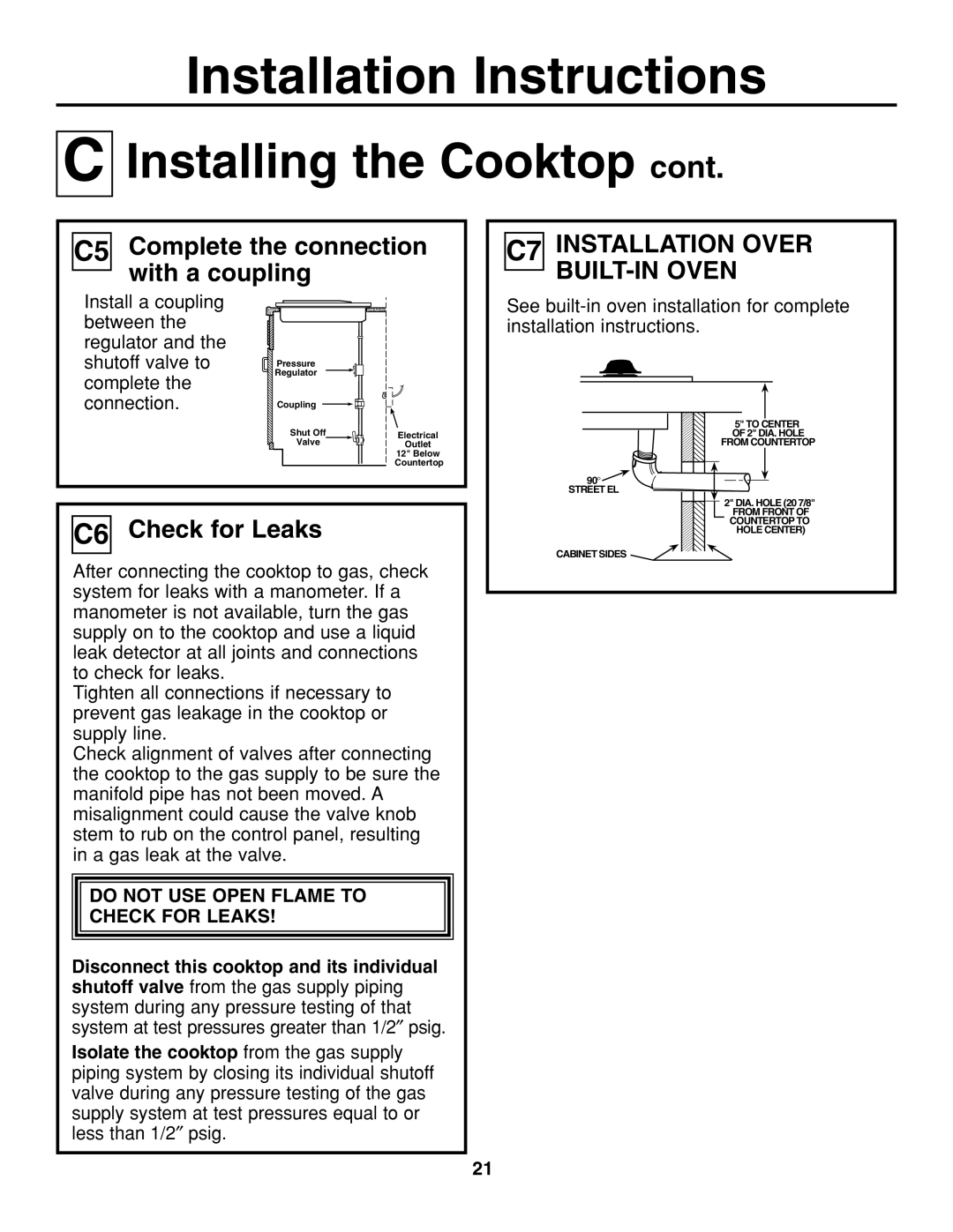
C7 INSTALLATION OVER BUILT-IN OVEN
Install a coupling between the regulator and the shutoff valve to complete the connection.
Pressure |
Regulator |
Coupling |
Shut Off |
Valve |
Electrical
Outlet
12" Below
Countertop
See
5" TO CENTER
OF 2" DIA. HOLE
FROM COUNTERTOP
90° ![]()
STREET EL
2" DIA. HOLE (20 7/8"
C6 Check for Leaks
After connecting the cooktop to gas, check system for leaks with a manometer. If a manometer is not available, turn the gas supply on to the cooktop and use a liquid leak detector at all joints and connections to check for leaks.
Tighten all connections if necessary to prevent gas leakage in the cooktop or supply line.
Check alignment of valves after connecting the cooktop to the gas supply to be sure the manifold pipe has not been moved. A misalignment could cause the valve knob stem to rub on the control panel, resulting in a gas leak at the valve.
DO NOT USE OPEN FLAME TO
CHECK FOR LEAKS!
Disconnect this cooktop and its individual shutoff valve from the gas supply piping system during any pressure testing of that system at test pressures greater than 1/2″ psig.
Isolate the cooktop from the gas supply piping system by closing its individual shutoff valve during any pressure testing of the gas supply system at test pressures equal to or less than 1/2″ psig.
FROM FRONT OF
COUNTERTOP TO
HOLE CENTER)
CABINET SIDES
21