Manuals
/
GE
/
Kitchen Appliance
/
Range
GE
JGBS04 Level The Range, Install The Anti-Tip Device, Installation Instructions, 2 1⁄ 8 ″
Models:
JGBS04
JGBS07
JGBS17
JGBS22
JGBS20
JGBS23
JGBS21
RGB508
RGB524
RGB528
RGB540
RGB533
JGSS05
1
38
48
48
Download
48 pages
28.93 Kb
35
36
37
38
39
40
41
42
Troubleshooting
Install
Warranty
Dimension
Problem
Accessories
Flexible Connector Hookup
To Adjust the Thermostat
Care and cleaning of the range
How to
Page 38
Image 38
Page 37
Page 39
Page 38
Image 38
Page 37
Page 39
Contents
Safety Instructions . . . .2-7 Operating Instructions
183D5580P155 49-85068 12-03 JR
Non-Self-Cleaning Gas
Care and Cleaning
Tips Installation Instructions Operating Instructions
IMPORTANT SAFETY INFORMATION READ ALL INSTRUCTIONS BEFORE USING
Safety Instructions
Consumer Support Troubleshooting
Safety Instructions Operating Instructions
IMPORTANT SAFETY NOTICE
SAFETY PRECAUTIONS
Installation Instructions Troubleshooting Tips Consumer Support
Consumer Support Troubleshooting Tips Installation Instructions
IMPORTANT SAFETY INFORMATION. READ ALL INSTRUCTIONS BEFORE USING
Operating Instructions Safety
Instructions
Safety Instructions Operating
COOK MEAT AND POULTRY THOROUGHLY…
OVEN
SURFACE BURNERS
SURFACE BURNERS cont
Safety
Installation Instructions Troubleshooting Tips Consumer Support
SAVE THESE INSTRUCTIONS
Tips Installation Instructions Operating
Using the gas surface burners
Support Troubleshooting
Instructions
How to Select Flame Size
Safety Instructions
Operating Instructions Installation
Consumer Support
Instructions Operating Instructions Safety Instructions
Using the clock and timer
Tips Installation
To Set the Kitchen Timer
Instructions Troubleshooting
Using the oven
Instructions Installation
Instructions Operating
Preheating and Pan Placement
Instructions Safety
How to Set the Oven for Baking or Roasting
Instructions Operating
How to Set the Oven for Broiling
Safety
Instructions Operating Instructions Installation Instructions
Tips Consumer Support
Bacon
Broiling Guide
Second Side
Ground Beef
Instructions Troubleshooting Tips Consumer Support
Adjust the oven thermostat-Do it yourself
Safety Instructions
To Adjust the Thermostat
Consumer Support Troubleshooting
Care and cleaning of the range
Tips Installation Instructions Operating Instructions
Standard Twin Burner Assemblies on some models
Safety
Instructions Operating Instructions
Burner Grates
NOTE Do not use steel wool or scouring powders to clean the burners
Burner caps
After cleaning
Replacement
Burner heads
Installation Instructions Troubleshooting
Cooktop Surface
To Order
Instructions Operating Instructions
Lift-Off Oven Door
Consumer Support Troubleshooting Tips
Installation Instructions Operating Instructions Safety Instructions
Oven Bottom
Removable Broiler Drawer on some models
Instructions Operating
Broiler Pan and Grid
Oven Air Vents
Oven Shelves
Cautions about using spray-on oven cleaners
Special Care of Continuous-Cleaning Oven Interior on some models
To Clean the Continuous-Cleaning Oven
Installation Instructions
IN THE COMMONWEALTH OF MASSACHUSETTS
BEFORE YOU BEGIN
Range
TOOLS YOU WILL NEED
Installation Instructions
FOR YOUR SAFETY
PART INCLUDED
MUST NEVER BE LESS THAN 24 INCHES
INSTALLATION SAFETY INSTRUCTIONS
24 INCHES
36 ″
DIMENSIONS AND CLEARANCES
The range may be placed with 0″ clearance flush at the back wall
1/4 ″
MODEL AND SERIAL NUMBER LOCATION
ANTI-TIP DEVICE
LOCATION
Take the accessory pack out of the oven and/or drawer
WARNING - DO NOT USE A FLAME TO CHECK FOR GAS LEAKS
2 CONNECT THE RANGE TO GAS
1 PROVIDE ADEQUATE GAS SUPPLY
Installation Instructions
Alternate Hookup
FLEXIBLE CONNECTOR HOOKUP for models equipped with Sealed Burners
RIGID PIPE HOOKUP OPTIONS for models equipped with Sealed Burners
Gas Flow into Range
RIGID PIPE HOOKUP for models equipped with Standard Twin Burners
FLEXIBLE CONNECTOR HOOKUP
for models equipped with Standard Twin Burners
Electrical Requirements
3 ELECTRICAL CONNECTIONS
FOR PERSONAL SAFETY, THIS APPLIANCE MUST BE PROPERLY GROUNDED
Extension Cord Cautions
5 LIGHT THE PILOTS
3 ELECTRICAL CONNECTIONS cont
4 SEAL THE OPENINGS
Electric Disconnect
C Light the Oven Pilot
5 LIGHT THE PILOTS cont
B Adjust the Surface Burner Pilots if Necessary
C Light the Oven Pilot cont
D Check Ignition of Oven Burner
To Remove the Broiler Drawer
Electric Ignition Models
F Check Ignition of Surface Burners
Standing Pilot Models
Quality of Flames
2 1⁄ 8 ″
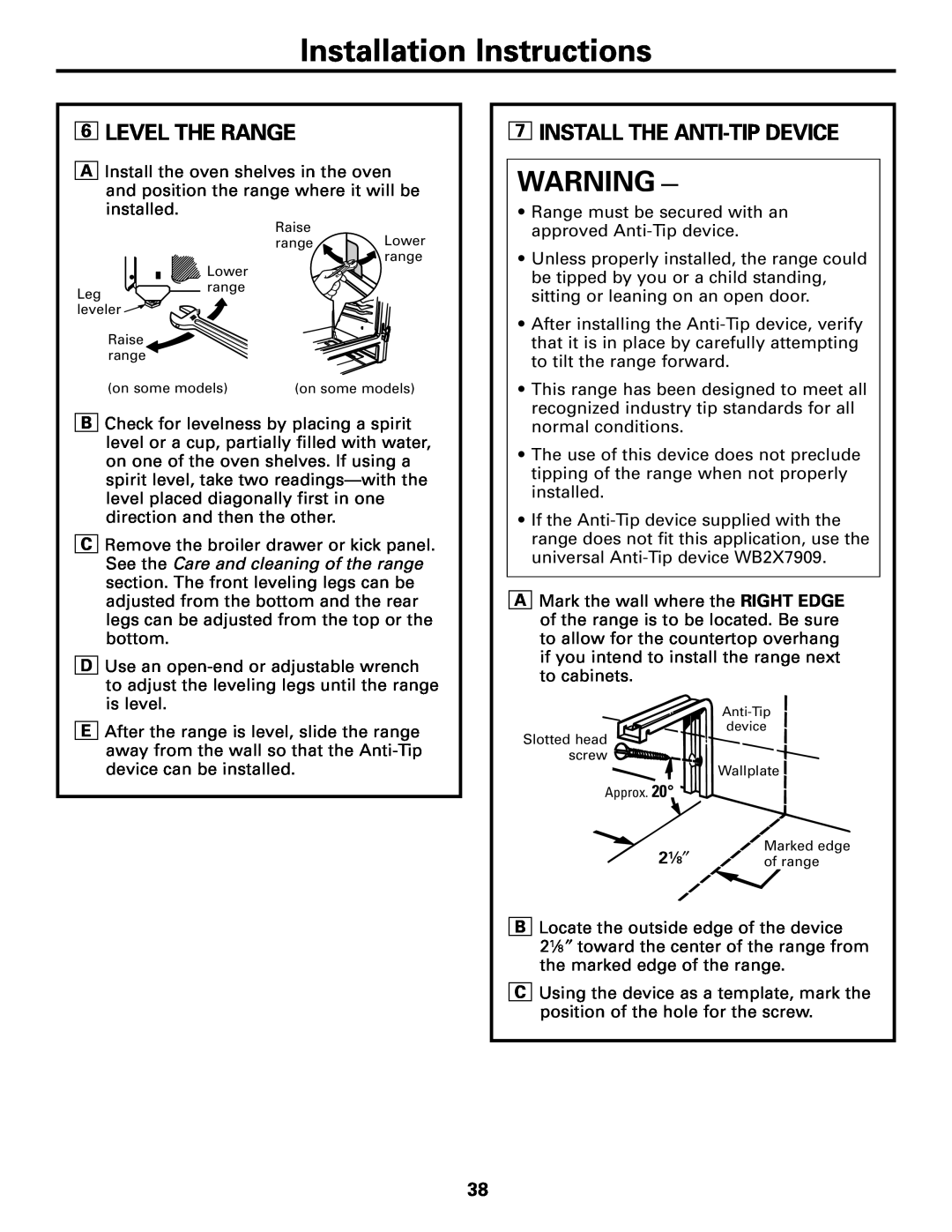
7 INSTALL THE ANTI-TIP DEVICE
6 LEVEL THE RANGE
CONVERT TO LP GAS or convert back to natural gas from LP
7 INSTALL THE ANTI-TIP DEVICE cont
WHEN ALL HOOKUPS ARE COMPLETED
See the Care and cleaning of the range section
Before you call for service…
Problem
Installation Instructions
See the Installation of the range section
See the Using the clock and timer section
See the Care and cleaning of the range section
See the Light the Oven Pilot section in the Installation
“popping” sound
Power outage
“Crackling” or
Rainbow effect in
General Electric Company
GE Service Protection Plus
Warranty Registration Department P.O. Box Louisville, KY
We’ll Cover Any Appliance. Anywhere. Anytime
Serial Number
Follow these three steps to protect your new appliance investment
Model Number
Consumer Product Ownership Registration
GE’s innovative, self-cleanable porcelain-coated oven racks
Accessories
Looking For Something More?
Heavy Duty Durable Able to be cleaned in a self-cleaning oven
GE Gas Range Warranty. For customers in the United States
Instructions Safety Instructions
Consumer Support Troubleshooting Tips Installation Instructions
Operating
Safety Instructions Operating
Instructions Troubleshooting Tips Consumer Support
Instructions Installation
GE Gas Range Warranty. For customers in Canada
Consumer Support
Schedule Service
Parts and Accessories
GE Appliances Website
Top
Page
Image
Contents