Installation Instructions
11MARK HOLES
Select the vent option that your installation will require and proceed to that section:
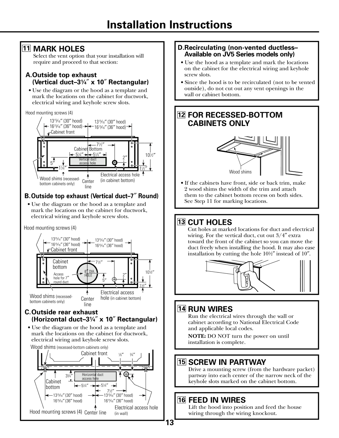
A.Outside top exhaust
(Vertical duct–31⁄4″ x 10″ Rectangular)
•Use the diagram or the hood as a template and mark the locations on the cabinet for ductwork, electrical wiring and keyhole screw slots.
Hood mounting screws (4) |
|
|
|
|
|
|
|
|
|
| ||
|
|
|
|
|
|
|
|
|
|
|
|
|
|
| 1315⁄16″ (30″ hood) |
|
|
|
|
|
|
|
|
|
|
|
|
|
|
| 13 | 15 | ⁄16 | ″ | (30 | ″ | hood) | |
|
| 1615⁄16″ (36″ hood) |
|
| ″ | ″ | ||||||
|
|
|
|
| 16 | 15 | ⁄16 | (36 | hood) | |||
|
|
|
|
| ||||||||
|
|
|
|
|
|
| ||||||
|
| Cabinet front |
|
|
|
|
|
|
|
|
|
|
|
|
|
|
|
|
|
|
|
|
|
| |
|
| 71⁄2″ |
|
|
| Cabinet Bottom |
|
| |
| 51⁄4″ | 51⁄4″ | 2″ | 101⁄2″ |
″ | Vertical duct |
| ||
access hole |
|
| ||
5 | 11⁄4″ |
|
| 11⁄2″ |
|
|
| ||
|
|
|
|
| Electrical access hole |
Wood shims (recessed- | Center | (in cabinet bottom) | |||
bottom cabinets only) | line |
| |||
|
|
| |||
B.Outside top exhaust (Vertical duct–7″ Round)
•Use the diagram or the hood as a template and mark the locations on the cabinet for ductwork, electrical wiring and keyhole screw slots.
Hood mounting screws (4)
1315⁄16″ (30″ hood) |
|
|
| 1315⁄16″ (30″ hood) |
1615⁄16″ (36″ hood) |
|
|
| 1615⁄16″ (36″ hood) |
![]() Cabinet front
Cabinet front
Cabinet |
| 71⁄2″ |
|
bottom | 8″ DIA. |
| 101⁄2″ |
Access | ″ | ||
hole for 7″ | HOLE | 2 |
|
| 5″ |
| |
round duct |
| 11⁄2″ | |
|
| ||
|
|
|
Electrical access
Wood shims (recessed- Center hole (in cabinet bottom) bottom cabinets only)
line
C.Outside rear exhaust
(Horizontal duct–31⁄4″ x 10″ Rectangular)
•Use the diagram or the hood as a template and mark the locations on the cabinet for ductwork, electrical wiring and keyhole screw slots.
Wood shims |
| |||
| Cabinet front | 1⁄8″ 3⁄4″ | ||
| 33⁄4″ | Horizontal duct |
| |
Cabinet |
| access hole |
|
|
51⁄4″ | 51⁄4″ |
| ||
bottom |
| |||
1315⁄16″ (30″ hood) |
| 71⁄2″ |
| |
| 1315⁄16″ (30″ hood) | |||
1615⁄16″ (36″ hood) |
| 1615⁄16″ (36″ hood) | ||
Electrical access hole
Hood mounting screws (4) Center line | (in wall) |
D.Recirculating
•Use the hood as a template and mark the locations on the cabinet for the electrical wiring and keyhole screw slots.
•Since the hood is to be recirculated (not to be vented outside), do not cut out any vent openings in the wall or cabinet bottom.
12FOR RECESSED-BOTTOM CABINETS ONLY
Wood shims
•If the cabinets have front, side or back trim, make 2 wood shims the width of the trim and attach them to the cabinet bottom recess on both sides. See Step 11 for marking locations.
13CUT HOLES
Cut holes at marked locations for duct and electrical wiring. For the vertical duct, cut out 3/4″ extra toward the front of the cabinet so you can move the duct freely when installing the hood. It may also ease installation by cutting the hole 101⁄2″ instead of 10″.
14RUN WIRES
Run the electrical wires through the wall or cabinet according to National Electrical Code and applicable local codes.
NOTE: DO NOT turn the power on until installation is complete.
15SCREW IN PARTWAY
Drive a mounting screw (from the hardware packet) partway into each center of the narrow neck of the keyhole slots marked on the cabinet bottom.
16FEED IN WIRES
Lift the hood into position and feed the house wiring through the wiring knockout.
13