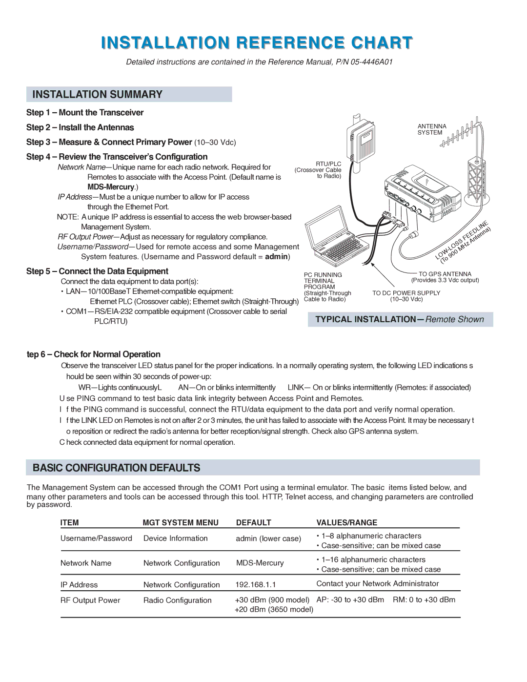
RTU/PLC (Crossover Cable to Radio)

INSTALLATION REFERENCE CHART

Detailed instructions are contained in the Reference Manual, P/N 05-4446A01

INSTALLATION SUMMARY

Step 1 – Mount the Transceiver

Step 2 – Install the Antennas

Step 3 – Measure & Connect Primary Power (10–30 Vdc)

Step 4 – Review the Transceiver’s Configuration

Network Name—Unique name for each radio network. Required for Remotes to associate with the Access Point. (Default name is MDS-Mercury.)

IP Address—Must be a unique number to allow for IP access through the Ethernet Port.

NOTE: A unique IP address is essential to access the web browser-based Management System.

RF Output Power—Adjust as necessary for regulatory compliance. Username/Password—Used for remote access and some Management

System features. (Username and Password default = admin)

Step 5 – Connect the Data Equipment

Connect the data equipment to data port(s):

LAN—10/100BaseT Ethernet-compatible equipment:

Ethernet PLC (Crossover cable); Ethernet switch (Straight-Through)

COM1—RS/EIA-232 compatible equipment (Crossover cable to serial PLC/RTU)

tep 6 – Check for Normal Operation

ANTENNA

SYSTEM


FEEDLINE


-LOSSMHz

Antenna)


LOW

900


(To


PC RUNNING

TO GPS ANTENNA

TERMINAL

(Provides 3.3 Vdc output)

PROGRAM

TO DC POWER SUPPLY


(Straight-Through


Cable to Radio)

(10–30 Vdc)


TYPICAL INSTALLATION—Remote Shown

Observe the transceiver LED status panel for the proper indications. In a normally operating system, the following LED indications s hould be seen within 30 seconds of power-up:

WR—Lights continuouslyL AN—On or blinks intermittently LINK— On or blinks intermittently (Remotes: if associated) U se PING command to test basic data link integrity between Access Point and Remotes.

I f the PING command is successful, connect the RTU/data equipment to the data port and verify normal operation.

If the LINK LED on Remotes is not on after 2 or 3 minutes, the unit has failed to associate with the Access Point. It may be necessary t o reposition or redirect the radio’s antenna for better reception/signal strength. Check also GPS antenna system.

C heck connected data equipment for normal operation.

BASIC CONFIGURATION DEFAULTS

The Management System can be accessed through the COM1 Port using a terminal emulator. The basic items listed below, and

many other parameters and tools can be accessed through this tool. HTTP, Telnet access, and changing parameters are controlled by password.

ITEM

MGT SYSTEM MENU

DEFAULT

VALUES/RANGE


Username/Password

Device Information

admin (lower case)

1–8 alphanumeric characters


Case-sensitive; can be mixed case


Network Name

Network Configuration

MDS-Mercury

1–16 alphanumeric characters


Case-sensitive; can be mixed case


IP Address

Network Configuration

192.168.1.1

Contact your Network Administrator


RF Output Power

Radio Configuration

+30 dBm (900 model)

AP: -30 to +30 dBm RM: 0 to +30 dBm


+20 dBm (3650 model)


Page 11
Image 11
GE MDS 05-4558A01 manual Installation Reference Chart, MGT System Menu Default VALUES/RANGE

MDS 05-4558A01 specifications

The GE MDS 05-4558A01 is a robust and versatile communication device designed primarily for industrial applications. This product is part of a larger line of GE MDS communication solutions that ensure reliable data transmission over various distances, making it a preferred choice for manufacturers and operators in sectors such as utilities, transportation, and various industrial settings.

One of the main features of the GE MDS 05-4558A01 is its ability to support multiple communication protocols. This adaptability allows integration into a variety of existing network setups, facilitating seamless connectivity and efficient data transfer. The device is equipped with advanced packet radio technology, which enhances its performance in noisy environments, a common challenge in industrial operations.

The GE MDS 05-4558A01 also boasts a high level of scalability. Users can easily expand their networks as their operational needs grow, ensuring that the communication infrastructure remains robust and future-proof. This scalability is crucial for industries that require both immediate and long-term data transmission solutions without significant reinvestment in new technologies.

In addition to its communication capabilities, the device features durable construction designed to withstand harsh environmental conditions. Its rugged design ensures reliability in extreme temperatures, humidity, and even exposure to dust and chemicals. This durability is coupled with a compact form factor, allowing for flexible installation in various locations and environments.

Another significant characteristic of the GE MDS 05-4558A01 is its low power consumption. Designed to operate efficiently, it minimizes energy usage while maintaining consistent performance. This feature is particularly important for remote installations where power resources may be limited.

The device also incorporates advanced security protocols to protect the integrity of transmitted data. By employing encryption techniques and secure authentication methods, the GE MDS 05-4558A01 ensures that sensitive information remains protected from unauthorized access.

Its user-friendly interface simplifies installation and management, enabling technicians to quickly configure and deploy the devices with minimal training. This ease of use is complemented by comprehensive technical support provided by GE, ensuring that users can maximize the performance of their communication infrastructure.

Overall, the GE MDS 05-4558A01 stands out for its integration of advanced technologies, robust features, and reliability, making it an exceptional choice for industries needing dependable and secure data communication solutions.