Installation Requirements (continued)-_RT~T...

Please Read Carefully

Use of Adapter Plug

Because of potential safety hazards under certain conditions, we strongly ~ommend againstuse of an adapter plug. However, if you still elect to use an adapter, where local codes permit, a TEMPORARY CONNECIION maybemadetoap~rlym

two-prong wall outlet by use of a UL listed adapter (Fig. 2) available at most local hardware stores.

TEMPORARYMETHOD

.=

IADAPTERPLUGSNOT


PERMITTEDIN CANAOA)

Utjrj 4

ALIGNLARGE

‘RONGs’sLOTs=

I ,,

- ‘ --


. _-

Qn

\


:2’


,J INSUREPROPERGROUNO

Fig. 2

w

;

‘-lX?oW!!#NNECTtON


The Iarger slot in the adapter must be aligned with the larger slot in the wall outlet to provide proper polarity in the connection of the power cord.

CAUTION: Attaching adapter ground terminal to wall outlet cover screw does not ground the appliance unless cover screw is metal, and not insulated, and walloutlet is grounded through house wiring. You should havethe circuit checked by a qwdified electrician to make sure the outlet is properly grounded.

When disconnecting the power cord from the adapter, alwayshold the adapter with one hand. If this is not done, the adapter ground terminal is very likely to break with repeated use.

Should the adapter ground terminal break, DO NOT USE the appliance until a proper ground has again been established.

Use of Extension Cords

Because of potential safety hazards under certain conditions, we strongly recommend against the use of an extension cord. However, if you still elect to use an extension cord, it is absolutely necessary that it be a UL listed 3-wire grounding type appliance extension cord having a grounding type plug and outlet and that the electrical rating of the

cord be 15amperes (minimum) and 120volts. Such extension cords are obtainable through your local service organization.

The refrigerator should always be plugged into its own individual electrical outlet—

(115volt, 60 Hertz, single phase AC). This is recommended for best performance and to prevent overloading house wiring circuits, which could cause a fire hazard from overheating wires.

Refrigerator Location

Donot install refrigerator where temperature will go below 60”F.

because it will not run often enough to maintain proper temperatures.

Do install it on a floor strong enough to support a fully loaded refrigerator.

Also see Energy-Saving Tips regarding location.

Clearances

A11owthe following clearances for ease of installation, proper air circulation, and plumbing and electrical connections:

Sides . . . . . . . . . . . . . . . . . . . ..~”

Top . . . . . . . . . . . . . . . . . . . . ..o” (If built in, allow 7/8”at the top for hinge covers.)

Back . . . . . . . . . . . . . . . . . . . . ..l”

Allow the following door clearance: Refreshment Center Side . . . . 3%” Freezer Side . . . . . . . . . . . . ..l~”

Water Supply to Icemaker

Youwill need to connect your icemaker to a cold water line. A water supply kit containing copper tubing, shut-offvalve, fittingsand instructions is available at extra cost from your dealer. There should be sufficient tubing for the icemaker from the cold water supply to allow you to move the refrigerator out from the wall several feet (approximately

3 coils of l/4-inch copper tubing that is at least 10inches in diameter).

Rollers

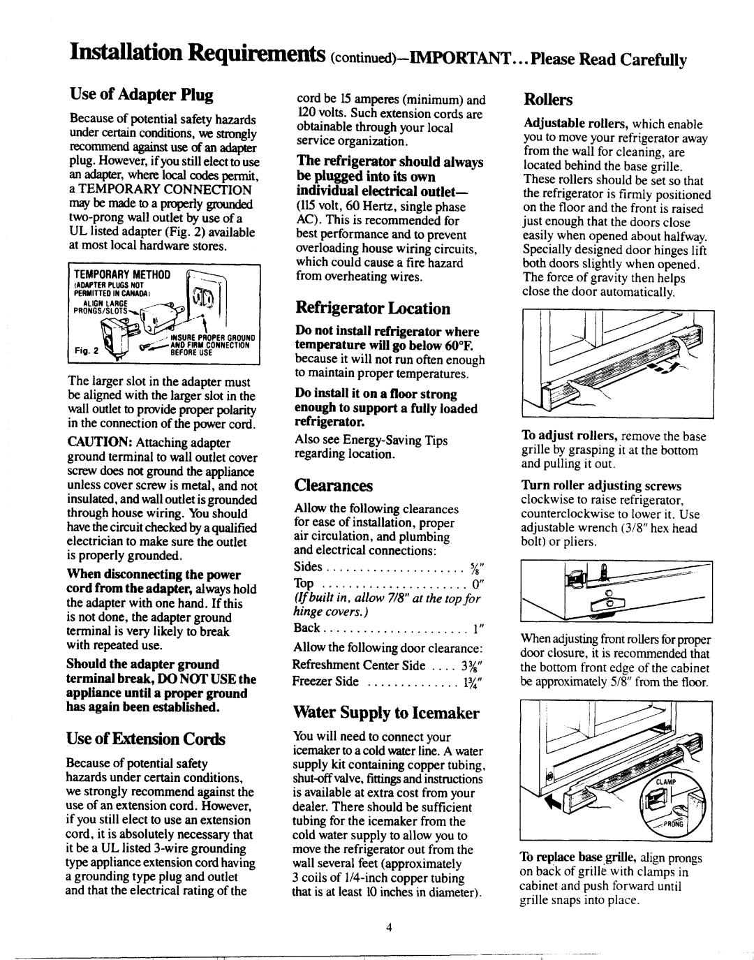
Adjustable rollers, which enable you to move your refrigerator away from the wall for cleaning, are located behind the base grille. These rollers should be set so that the refrigerator is firmly positioned on the floor and the front is raised just enough that the doors close easily when opened about halfway. Specially designed door hinges lift both doors slightly when opened. The force of gravity then helps close the door automatically.

To adjust rollers, remove the base

grille by grasping it at the bottom and pulling it out.

Turn roller adjusting screws

clockwise to raise refrigerator, counterclockwise to lower it. Use adjustable wrench (3/8” hex head bolt) or pliers.

Whenadjusting front rollers for proper door closure, it is recommended that the bottom front edge of the cabinet be approximately 5/8” from the floor.

t

To replace b=cgril.ie, align prongs on back of grille with clamps in cabinet and push forward until grille snaps into place.

4

I

1

,. ,I

—-..——...— .

——.

,– -..

II

I

I

I II

I

I


Page 4
Image 4
GE Numbers 2 warranty Installation Requirements -RT~T

Numbers 2 specifications

The GE Numbers 2 represents a significant leap in advanced technology and engineering design, showcasing General Electric's commitment to innovation. This cutting-edge machine is engineered to meet the ever-evolving demands of various industries, including energy, transportation, and manufacturing.

One of the standout features of GE Numbers 2 is its high efficiency. The system is designed to optimize performance while reducing energy consumption, which is essential in today’s cost-sensitive environment. This efficiency is achieved through advanced predictive analytics that monitor operational performance in real time, allowing for immediate adjustments to maintain optimal conditions.

Moreover, the GE Numbers 2 incorporates state-of-the-art materials and engineered components, enhancing durability and reliability. The use of lightweight yet robust materials contributes to the overall performance while minimizing maintenance needs. This quality makes it particularly advantageous for harsh operating conditions, ensuring longevity and a lower total cost of ownership.

In terms of technology, GE Numbers 2 integrates the latest automation and control systems. It utilizes artificial intelligence and machine learning algorithms to analyze data collected from its various sensors. This data-driven approach enables proactive maintenance strategies, ultimately reducing downtime and enhancing productivity.

Connectivity is another critical feature of GE Numbers 2. With its advanced IoT capabilities, the machine can integrate seamlessly with existing infrastructure. This connectivity allows for remote monitoring and management, providing operators with the flexibility to oversee operations from anywhere.

The design of GE Numbers 2 focuses on user experience and accessibility. Its intuitive interface simplifies operation, enabling users to make quick adjustments and monitor performance metrics easily. This usability is coupled with extensive training resources and support, ensuring that operators can leverage the machine’s full potential.

Additionally, GE Numbers 2 places a strong emphasis on sustainability. The machine's design and operation focus on minimizing environmental impact, aligning with global efforts toward greener technology. This commitment to sustainability is not only good for the environment but also resonates with customers looking to enhance their corporate social responsibility profiles.

In summary, GE Numbers 2 is a testament to General Electric's innovative spirit, combining efficiency, advanced technology, and sustainability to deliver solutions that meet the needs of modern industries. Its robust features and intelligent connectivity make it a valuable asset for businesses aiming to excel in a competitive landscape.