g
GE Capacitor & Power Quality Products
INSTALLATION INSTRUCTIONS - continued
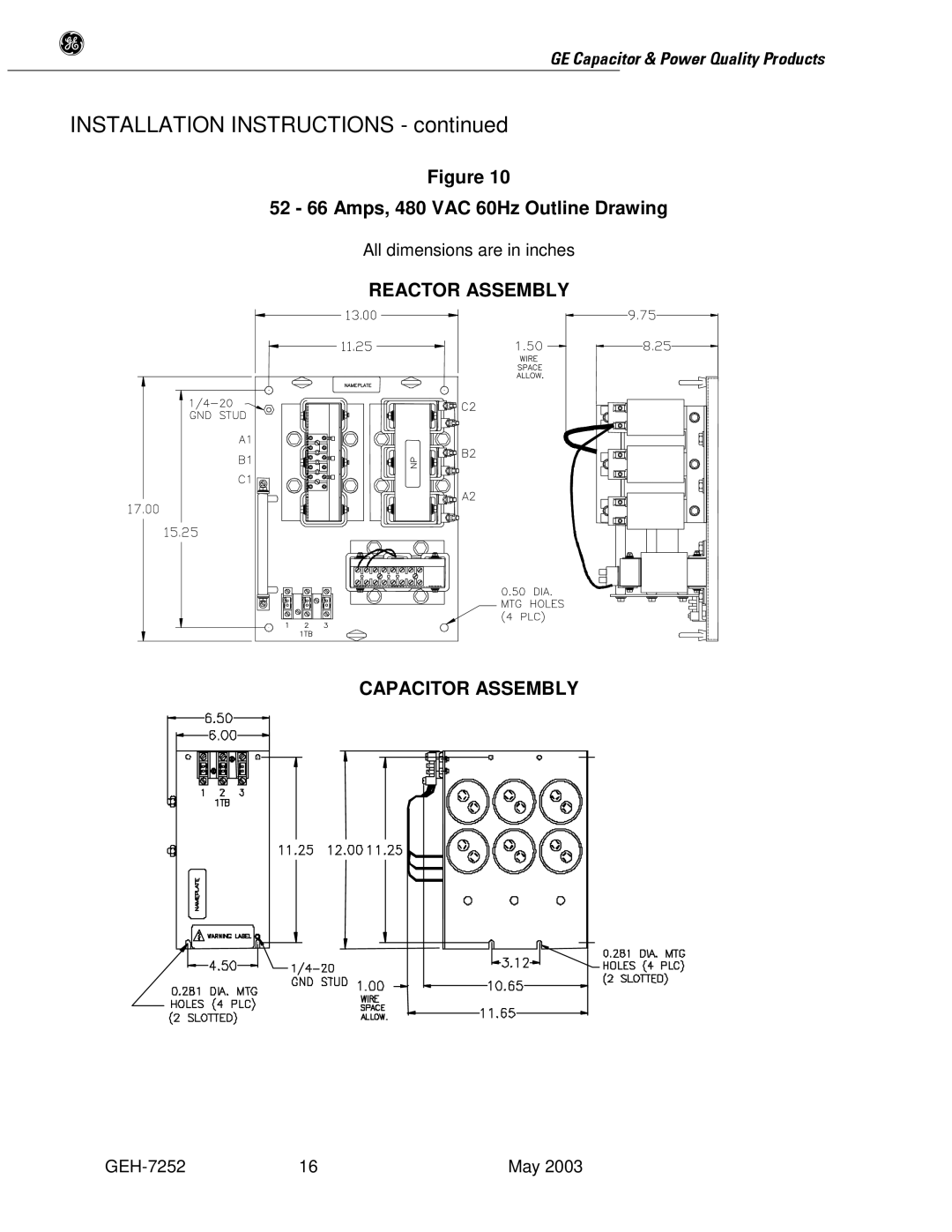
Figure 10
52 - 66 Amps, 480 VAC 60Hz Outline Drawing
All dimensions are in inches
REACTOR ASSEMBLY
CAPACITOR ASSEMBLY
16 | May 2003 |
g
Figure 10
All dimensions are in inches
REACTOR ASSEMBLY
CAPACITOR ASSEMBLY
16 | May 2003 |