3
Wiring
To wire the module, do the following:
1.Remove AC panel power and disconnect the backup battery.
CAUTION: To prevent damaging the panel or module, you must remove panel AC power and disconnect the backup battery before making or changing wiring connections.
2.Wire the module to the panel bus and to the battery termi- nals for power (Figure 5).
Note: The module can also be powered off the SuperBus 2000 two amp power supply
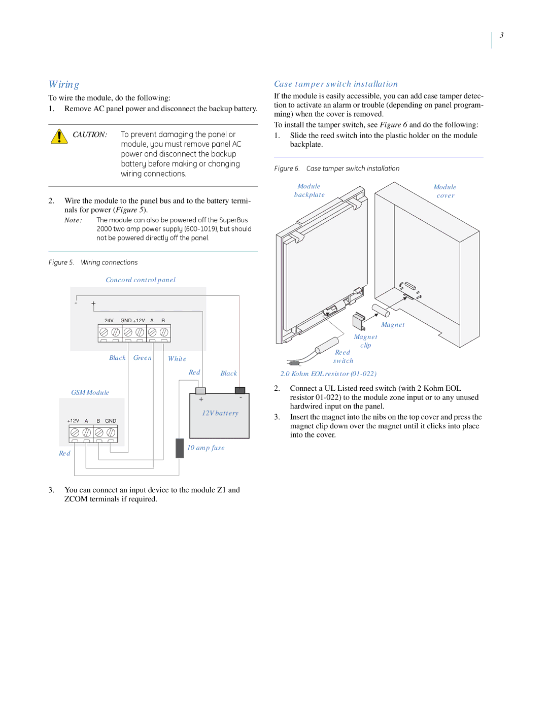
Case tamper switch installation
If the module is easily accessible, you can add case tamper detec- tion to activate an alarm or trouble (depending on panel program- ming) when the cover is removed.
To install the tamper switch, see Figure 6 and do the following:
1.Slide the reed switch into the plastic holder on the module backplate.
Figure 6. Case tamper switch installation
Module | Module |
backplate | cover |
Figure 5. Wiring connections
Concord control panel
-+
24V GND +12V A B
Black Green | White |
|
| Red | Black |
GSM Module | + | - |
| ||
| 12V battery | |
+12V A B GND |
|
|
Red | 10 amp fuse | |
|
| |
3.You can connect an input device to the module Z1 and ZCOM terminals if required.
Magnet
Magnet clip
Reed switch
2.0Kohm EOL resistor
2.Connect a UL Listed reed switch (with 2 Kohm EOL resistor
3.Insert the magnet into the nibs on the top cover and press the magnet clip down over the magnet until it clicks into place into the cover.