4
SuperBus 2000 Concord 4 GSM Module
Installation Instructions
Power up
To power up the module and panel and start communication between them, do the following:
1.Verify that all wiring between the panel and module is correct.
2.Connect the backup battery and restore AC power to the panel.
Note: Whenever any module is added or changed, you must remove panel power and reapply it for the panel and module to communicate successfully.
3.Enter installer program mode and turn off the Access Code Lock feature (Security menu). This must be set to off for the system to communicate with Alarm.com. The module PWR LED should turn on. After a few seconds, the module BUS and AUTO LEDs should flash to indicate successful communication with the panel.
4.Verify that GSM status LED 1 is not flashing any errors (see GSM status LEDs on page 5). Also, verify that LED 4 is at least flashing a level of two. Otherwise, relocate the module. If LED 1 and LED 4 are not flashing at all, and LED 2 and LED 3 are flashing together, the module is in PowerSave mode and the battery needs to be charged.
5.Do an installer GSM manual phone test (at a system touchpad, enter 8, installer code, 3). Disarm the panel by entering 1, installer code within 10 seconds of starting the phone test. Before doing the manual phone test, the bottom red status LED should be on and the yellow status LED should be flashing. The yellow LED will stay on solid once the manual phone test is completed.
Note: Do not press any system touchpad buttons during the five to eight minutes or the time will not set. During this time, the keypad will go in and out of programming mode and will beep several times.
Status LEDs
The status LEDs, located on the left side of the module (Figure 1 on page 1) indicate the current signal and status of the Wireless Gateway Module. The bottom red LED indicates if the module is in range and if it is registered. The yellow and green LEDs indi- cate the message status. The top LED is not used.
Red LED
On. When the module is in range and registered with the network.
Off. When the module is out of range and not registered with the network.
Blinks. When the module is registered with the network, but out of range.
Yellow LED
On. After the first message has been sent by the module and received by Alarm.com.
Off. Until a message has been sent by the module.
Blinks. When the first message is being sent by the module.
Green LED
Off. As soon as Alarm.com receives the message from the module (off most of the time).
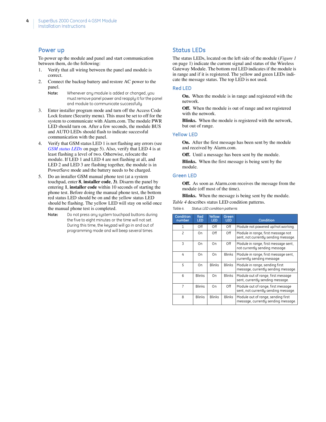
Blinks. When the message is being sent by the module. Table 4 describes status LED condition patterns.
Table 4. | Status LED condition patterns | |||
|
|
|
|
|
Condition | Red | Yellow | Green |
|
number | LED | LED | LED | Condition |
1 | Off | Off | Off | Module not powered up/not working. |
|
|
|
|
|
2 | On | Off | Off | Module in range, first message not |
|
|
|
| sent, not currently sending message. |
|
|
|
|
|
3 | On | On | Off | Module in range, first message sent, |
|
|
|
| not currently sending message. |
|
|
|
|
|
4 | On | On | Blinks | Module in range, first message sent, |
|
|
|
| currently sending message. |
|
|
|
|
|
5 | On | Blinks | Blinks | Module in range, sending first |
|
|
|
| message, currently sending message. |
|
|
|
|
|
6 | Blinks | On | Blinks | Module out of range, first message |
|
|
|
| sent, currently sending message. |
|
|
|
|
|
7 | Blinks | On | Off | Module out of range, first message |
|
|
|
| sent, not currently sending message. |
|
|
|
|
|
8 | Blinks | Blinks | Blinks | Module out of range, sending first |
|
|
|
| message, currently sending message. |
|
|
|
|
|