Manuals
/
GE
/
Kitchen Appliance
/
Range
GE
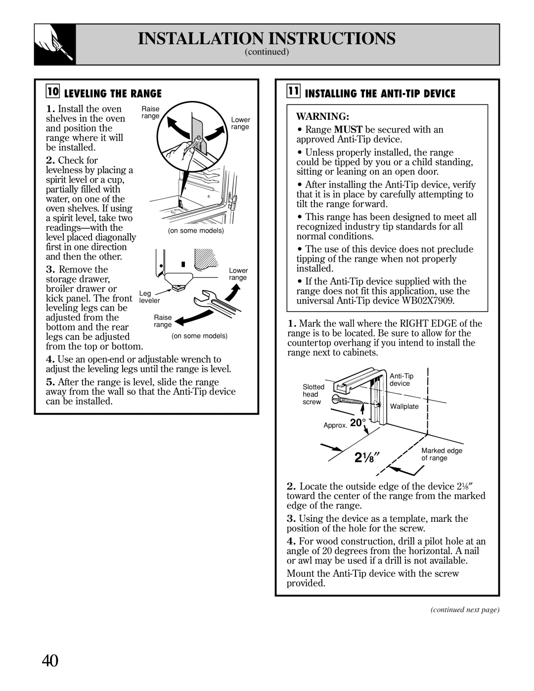
XL44 2 1⁄ 8 ″, Installation Instructions, Leveling The Range, Installing The Anti-Tip Device
Models:
XL44
1
40
48
48
Download
48 pages
12.36 Kb
37
38
39
40
41
42
43
44
Install
FAQ
Clock and Timer on some models
Warranty
Dimension
Problem
Parts and Accessories
Connector
Adjust The Oven Thermostat
Cleaning Your Range
Page 40
Image 40
Page 39
Page 41
Page 40
Image 40
Page 39
Page 41
Contents
Safety Instructions
Installation
Care and Cleaning
RangesXL44 Gas
Save time and money. Before you request service…
HELP US HELP YOU…
WHAT TO DO IF YOU SMELL GAS
Read this manual carefully
IMPORTANT SAFETY INSTRUCTIONS
Important Safety Instructions
Read all instructions before using this appliance
IMPORTANT SAFETY NOTICE
Surface Cooking
SAVE THESE INSTRUCTIONS
Cleaning Your Range
Baking, Broiling and Roasting
Features and appearance vary
FEATURES OF YOUR RANGE
MASK FOR SHELVES
Features of Your Range
Oven Light On/Off Switch on some models
Clock and Timer on some models
See page
SURFACE COOKING
Surface Burner Controls
Before Lighting a Burner
To Light a Surface Burner
Top-of-Range Cookware
How to Select Flame Size
Do not use a wok on any other support ring
CLOCK AND TIMER
To Set the Timer
To Change or Cancel the Timer Setting
Display Clock While Timer Is Operating
USING YOUR OVEN
and Timer
Using Your Oven
Before Using Your Oven
Oven Shelves
Shelf Positions
Oven Vents
locks so when placed
How to Set Your Range for Baking
BAKING
Baking
To avoid possible burns, place the shelves in the
Pan Placement
Preheating
Baking Guides
Cookies
Pies
Cakes
Baking Pans
Don’t Peek
ADJUST THE OVEN THERMOSTAT
The Type of Margarine Will Affect Baking Performance
To Adjust the Thermostat
DO IT YOURSELF
ROASTING
Roasting
Use of Aluminum Foil
Dual Shelf Cooking
Questions and Answers
ROASTING GUIDE
Frozen Roasts
Q. Why is my roast crumbling when I try to
BROILING
Broiling
Q. When broiling, is it necessary to always use a grid in the pan?
Q. Why are my meats not turning out as brown as they should?
BROILING GUIDE
The oven and broiler compartment doors must be closed during broiling
CARE AND CLEANING
Cleaning
Guide Care and
Standard Twin Burners on some models
Sealed Burner Assemblies on some models
For proper ignition
Grate Burner cap Drip pan on some models Burner head Electrode
Electrode
Care and Cleaning
Burner Grates
Cooktop Surface
Oven Bottom
Oven Light Bulb on some models
Control Panel and Knobs
Removable Broiler Drawer on some models
Broiler Pan and Grid
Care and Cleaning
Oven Air Vents
Removable Storage Drawer on some models
Removable Kick Panel on some models
Lift-Off Oven Door
TO CLEAN THE DOOR Do not immerse door in water Inside of door
Cautions about using spray-on oven cleaners
Outside of door
Special Care of Continuous-Cleaning Oven Interior on some models
Stainless Steel Surfaces on some models
To Clean the Continuous-Cleaning Oven
Do not scrape the porous surface with a knife or
INSTALLATION INSTRUCTIONS
FOR YOUR SAFETY
In the Commonwealth of Massachusetts
BEFORE YOU BEGIN
DIMENSIONS AND CLEARANCES
361⁄4″± 1⁄4″
36 ″
40 ″
GENERAL
IMPORTANT SAFETY INSTRUCTIONS
LOCATION
PROTECT YOUR FLOOR
KITCHEN CABINETS
TOOLS YOU WILL NEED
PREPARATION
1 PROVIDE ADEQUATE GAS SUPPLY
2 CONNECT THE RANGE TO GAS
Gas Pipe and Electric Outlet Locations
for Models Equipped with Sealed Burners
Flexible Connector Hookup for Models Equipped with Sealed Burners
Connector
Alternate Hookup
Rigid Pipe Hookup Options for Models Equipped with Sealed Burners
2 CONNECT THE RANGE TO GAS continued
3 ELECTRICAL CONNECTIONS on some models
Grounding
CAUTION DO NOT USE A FLAME TO CHECK FOR GAS LEAKS
Electric Disconnect
4 SEAL THE OPENINGS
Adjust the Surface Burner Pilots if Necessary
5 LIGHT THE PILOTS
Light the Surface Burner Pilots
Light the Oven Pilot
6 CHECK IGNITION OF SURFACE BURNERS
Quality of Flames
7 CHECK IGNITION OF OVEN BURNER
A Yellow flames
Air adjustment shutter Loosen
Loosen Air adjustment shutter
To remove the oven bottom
Oven bottom
1. Remove knurled screws holding down rear of oven bottom
To remove the broiler drawer
11 INSTALLING THE ANTI-TIP DEVICE
2 1⁄ 8 ″
10 LEVELING THE RANGE
MAKE SURE ALL CONTROLS ARE LEFT IN THE OFF POSITION
WHEN ALL HOOKUPS ARE COMPLETED
CONVERTING TO LP GAS
Page
QUESTIONS? BEFORE YOU CALL FOR SERVICE…
Before You Call for Service
PROBLEM
POSSIBLE CAUSE
BEFORE YOU CALL FOR SERVICE…
Do It Yourself section
GE Service Protection Plus
Warranty Registration Department P.O. Box Louisville, KY
Unlimited service calls All parts and labor costs included
We’ll Cover Any Appliance. Anywhere. Anytime
online at GEAppliances.com
Follow these three steps to protect your new appliance investment
Model Number
Serial Number
Schedule Service
Parts and Accessories
Consumer Support
GE Appliances Website
WARRANTY
under warranty
WHAT IS COVERED
WHAT IS NOT COVERED
Top
Page
Image
Contents