Sequence of Operation

Standard Transition

Source 1 Power Failure:

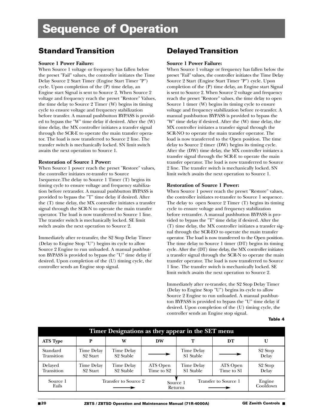
When Source 1 voltage or frequency has fallen below the preset "Fail" values, the controller initiates the Time Delay Source 2 Start Timer (Engine Start Timer "P") cycle. Upon completion of the (P) time delay, an Engine start Signal is sent to Source 2. When Source 2 voltage and frequency reach the preset "Restore" Values, the time delay to Source 2 Timer (W) begins its timing cycle to ensure voltage and frequency stabilization before transfer. A manual pushbutton BYPASS is provid- ed to bypass the "W" time delay if desired. After the (W) time delay, the MX controller initiates a transfer signal through the SCR-E to operate the main transfer opera- tor. The load is now transferred to Source 2 line. The transfer switch is mechanically locked. SN limit switch awaits the next operation to Source 1.

Restoration of Source 1 Power:

When Source 1 power reach the preset "Restore" values, the controller initiates re-transfer to Source 1sequence.The delay to Source 1 Timer (T) begins its timing cycle to ensure voltage and frequency stabiliza- tion before retransfer. A manual pushbutton BYPASS is provided to bypass the "T" time delay if desired. After the (T) time delay, the MX controller initiates a transfer signal through the SCR-N to operate the main transfer operator. The load is now transferred to Source 1 line. The transfer switch is mechanically locked. SE limit switch awaits the next operation to Source 2.

Immediately after re-transfer, the S2 Stop Delay Timer (Delay to Engine Stop "U") begins its cycle to allow Source 2 Engine to run unloaded. A manual pushbut- ton BYPASS is provided to bypass the "U" time delay if desired. Upon completion of the (U) timing cycle, the controller sends an Engine stop signal.

Delayed Transition

Source 1 Power Failure:

When Source 1 voltage or frequency has fallen below the preset "Fail" values, the controller initiates the Time Delay Source 2 Start (Engine Start Timer "P") cycle. Upon completion of the (P) time delay, an Engine start Signal is sent to Source 2. When Source 2 voltage and frequency reach the preset "Restore" values, the time delay to open Source 1 timer (W) begins its timing cycle to ensure voltage and frequency stabilization before re-transfer. A manual pushbutton BYPASS is provided to bypass the "W" time delay if desired. After the (W) time delay, the MX controller initiates a transfer signal through the SCR-NO to operate the main transfer operator. The load is now transferred to the Open position. The time delay to Source 2 timer (DW) begins its timing cycle. After the (DW) time delay, the MX controller initiates a transfer signal through the SCR-E to operate the main transfer operator. The load is now transferred to Source 2 line. The transfer switch is mechanically locked. SN limit switch awaits the next operation to Source 1.

Restoration of Source 1 Power:

When Source 1 power reach the preset "Restore" values, the controller initiates re-transfer to Source 1 sequence. The delay to open Source 2 Timer (T) begins its timing cycle to ensure voltage and frequency stabilization before retransfer. A manual pushbutton BYPASS is pro- vided to bypass the "T" time delay if desired. After the

(T)time delay, the MX controller initiates a transfer sig- nal through the SCR-EO to operate the main transfer operator. The load is now transferred to the Open position. The time delay to Source 1 timer (DT) begins its timing cycle. After the (DT) time delay, the MX controller initiates a transfer signal through the SCR-N to operate the main transfer operator. The load is now transferred to Source 1 line. The transfer switch is mechanically locked. SE limit switch awaits the next operation to Source 2.

Immediately after re-transfer, the S2 Stop Delay Timer (Delay to Engine Stop "U") begins its cycle to allow Source 2 Engine to run unloaded. A manual pushbut- ton BYPASS is provided to bypass the "U" time delay if desired. Upon completion of the (U) timing cycle, the controller sends an Engine stop signal.

Table 4

Timer Designations as they appear in the SET menu

ATS Type

P


W


DW


T


DT

U


Standard

Time Delay

Time Delay


Time Delay


S2 Stop

Transition

S2 Start


S2 Stable


S1 Stable


Delay


Delayed

Time Delay

Time Delay


ATS Open

Time Delay


ATS Open

S2 Stop

Transition

S2 Start


S2 Stable


Time to S2

S1 Stable


Time to S1

Delay


Source 1

Transfer to Source 2


Source 1

Transfer to Source 1

Engine

Fails


Cooldown


Returns


20

ZBTS / ZBTSD Operation and Maintenance Manual (71R-4000A)

GE Zenith Controls


Page 22
Image 22
GE ZBTSD manual Sequence of Operation, Timer Designations as they appear in the SET menu

ZBTS, ZBTSD specifications

General Electric (GE) has established itself as a leader in the field of industrial automation and control systems, with its ZBTSD and ZBTS series representing some of the most advanced technology available. These systems are engineered to enhance performance, efficiency, and reliability in various industrial applications.

The ZBTSD, or Zero-Based Time Series Data, is designed to optimize data storage and retrieval processes. One of its main features is its ability to provide real-time monitoring and analytics of dynamic processes. This capability is crucial for industries that require immediate insights into their operations, helping to minimize downtime and enhance decision-making. The ZBTSD utilizes advanced machine learning algorithms to identify trends and patterns, enabling predictive maintenance that can significantly reduce operational costs.

On the other hand, the ZBTS, or Zero-Based Time Series Solutions, focuses on delivering comprehensive solutions for time series data management. This system is adept at handling vast amounts of data generated by industrial equipment, ensuring that organizations can efficiently process and analyze this information. Key characteristics of ZBTS include scalability, which allows companies to expand their systems as their data grows, and flexibility, permitting integration with various data sources.

One notable technology employed in both ZBTSD and ZBTS is cloud computing. By leveraging the cloud, these systems offer enhanced data accessibility and collaboration capabilities. Users can access critical data anytime, anywhere, facilitating timely responses to operational challenges.

Another significant feature is robust cybersecurity measures. With the increasing number of cyber threats in industrial environments, GE has prioritized security in the ZBTSD and ZBTS systems. These solutions are equipped with advanced encryption protocols and user authentication mechanisms to protect sensitive data from unauthorized access.

The user interface of both systems is designed to be intuitive, allowing operators to interact with the systems efficiently. Customizable dashboards provide visual representations of key performance indicators, making it easier for users to comprehend complex data at a glance.

In summary, GE's ZBTSD and ZBTS systems exemplify the integration of cutting-edge technology in industrial automation. Their emphasis on real-time data analytics, scalability, cybersecurity, and user-friendly design positions them as invaluable tools for organizations seeking to enhance operational efficiency and decision-making. As industries continue to evolve, these systems will play a pivotal role in shaping the future of industrial automation and data management.